DIY 3 phase power distro

This is a panel board supplying 4no ETC sensor pro dimmers.

bdd7715c.jpg


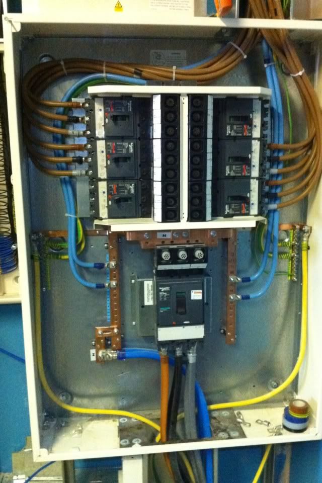
It's supplied by 2no 120mm² SWAs in parallel to account for the harmonic currents.
 
Sponsored Links
[pedant]

I'd count that as a doubling of all the conductors though, rather than a doubled neutral. Also the neutrals from panel board to dimmer appear to be the same size as the phase conductors...

[/pedant]

Of course if they're all oversized for the load then it hardly matters, so point taken.

I was thinking more about touring systems though, and the American habit of actually using two seperate neutral cables on things like this....

View media item 92456
where we only use one

View media item 92458
 
Every cable was over sized. The feed to the panel board was 400A and the supply to each dimmer was 80A on 35mm² tri rated conductors.

I guess it was easier from a design point of view to overrate every conductor rather than just the neutral.

I accept that there may be an issue with powerlock supplies to touring dimmers, but I'd like to hope that the supply to modern in house distros takes harmonic currents into the supply design.

At the touring house I work in, our powerlocks only have a 250A per phase supply, but the touring companies always use tails rated for 400A, and I beleive this is a standard setup throughout the industry.
 
I wonder if there would be a market for dimmers that don't have terrible power factor. With modern power electronics I would think it would be perfectly doable.
 
Sponsored Links
I wonder if there would be a market for dimmers that don't have terrible power factor. With modern power electronics I would think it would be perfectly doable.
You're probably right. Whether or not there would be a market presumably would depend largely on cost - and also education of those who do the buying, most of whom are probably unaware of any downsides of present devices, hence the advantages of a 'better' (and presumably more expensive) alternative.

Kind Regards, John
 
Heck with the right electronics you could probablly get to the level where a neutral shared between tens of channels needs to be only a few times bigger than the live conductors.
 
Heck with the right electronics you could probablly get to the level where a neutral shared between tens of channels needs to be only a few times bigger than the live conductors.
I'm not sure that the number of channels is all that important, is it - there will still only be three phases? However, it would be presumably be theoretically possible to create a (probably inefficient and impractical) dimmer which produced a more-or-less pure sine wave output, essentially no harmonics and which had a PF very close to 1, in which case the neutral conductor would probably not have to be any bigger than the live ones - provided that the loads themselves were essentially resistive (is that the case?).

Kind Regards, John
 
I was thinking of a topology where the incoming mains supplies a biploar DC bus (with active power factor correction on the input stage) and then the lights were driven by inverters off that DC bus. Similar to how a double conversion UPS works.

By monitoring the output neutral current and dynamically altering the phasing of the output inverters you could then keep the neutral current in the output circuits close to zero regardless of what set of lights was illuminated and to what power level.

As for "inefficient and impractical" witness PC power supplies. Until fairly recently they had awful efficiency and awful power factor. Nowadays the good ones have efficiencies of 90%+ and power factors very close to 1.
 
I was thinking of a topology where the incoming mains supplies a biploar DC bus (with active power factor correction on the input stage) and then the lights were driven by inverters off that DC bus. Similar to how a double conversion UPS works.
Yes, that's the sort of approach I was thinking about. Going via DC is certainly a good start, but if one wanted inverters with a variable voltage sine wave output, that might be more of a challenge.
By monitoring the output neutral current and dynamically altering the phasing of the output inverters you could then keep the neutral current in the output circuits close to zero regardless of what set of lights was illuminated and to what power level.
True, but I don't think that one would really need to go quite that far. Provided only that the 'dimmers' presented the supply with a PF close to unity (and that minimal harmonics generated), the neutral current could not rise to above the highest of the phase currents, no matter how imbalanced (in magnitude) were the loads on the three phases.
As for "inefficient and impractical" witness PC power supplies. Until fairly recently they had awful efficiency and awful power factor. Nowadays the good ones have efficiencies of 90%+ and power factors very close to 1.
I suppose that's true, although I didn't realise that they had got as good as you suggest. However, as above, it's easier when one wants fixed-voltage outputs.

Kind Regards, John
 
I was thinking of a topology where the incoming mains supplies a biploar DC bus (with active power factor correction on the input stage) and then the lights were driven by inverters off that DC bus. Similar to how a double conversion UPS works.
Yes, that's the sort of approach I was thinking about. Going via DC is certainly a good start, but if one wanted inverters with a variable voltage sine wave output, that might be more of a challenge.
Afaict fast PWM into a big inductor is the normal way of generating a reasonablly clean sinewave from a DC bus.

Provided only that the 'dimmers' presented the supply with a PF close to unity (and that minimal harmonics generated), the neutral current could not rise to above the highest of the phase currents, no matter how imbalanced (in magnitude) were the loads on the three phases.
Think of say a 30 channel 10 amp per channel dimmer.

With a "three phase" approach then even with unity power factor your output neutral would need to take up to 100A. Unless you had a lot of capacitance on the DC bus your input neutral would too. With a "dynamic phase" approach your neutral currents on both input and output could be practically zero.

Also with the dynamic phase approach it would be less important to have a high waveform purity on the output. In a three phase system third harmonics sum in the neutral but in a system with effectively tens of phases harmonic summing in the neutral would be far less of an issue.
 
Provided only that the 'dimmers' presented the supply with a PF close to unity (and that minimal harmonics generated), the neutral current could not rise to above the highest of the phase currents, no matter how imbalanced (in magnitude) were the loads on the three phases.
Think of say a 30 channel 10 amp per channel dimmer. ... With a "three phase" approach then even with unity power factor your output neutral would need to take up to 100A. Unless you had a lot of capacitance on the DC bus your input neutral would too. With a "dynamic phase" approach your neutral currents on both input and output could be practically zero.
True - but I thought what we were talking about was the potential neutral current in a 3-phase system, weren't we?

As for your example, a "30 channel 10A per channel dimmer" spread across three phases (i.e. 10 channels per phase) would require a maximum of 100A in each line conductor and, as you say, up to 100A in the neutral (if PF was close to 1 and harmonics were minimal). The neutral would therefore have to have no greater a CSA than the phase conductors - which is what most cables will give you.
Also with the dynamic phase approach it would be less important to have a high waveform purity on the output. In a three phase system third harmonics sum in the neutral but in a system with effectively tens of phases harmonic summing in the neutral would be far less of an issue.
As above, I thought you were still talking about 3-phase, not 'multiple dynamic phases'. I agree that multiple phases would usually result in less harmonic summation in the neutral, but one presumably would still have to design on the basis of possibly very unbalanced loads (maybe even just 3 of the phases being loaded!).

Kind Regards, John
 
As for your example, a "30 channel 10A per channel dimmer" spread across three phases (i.e. 10 channels per phase) would require a maximum of 100A in each line conductor and, as you say, up to 100A in the neutral (if PF was close to 1 and harmonics were minimal). The neutral would therefore have to have no greater a CSA than the phase conductors
Sure that is true on the input side.

Taking my example configuration on the output side you have 30 lives each rated at 10A each, then you have a neutral which with the three-phase approach could be carrying up to 100A.


As above, I thought you were still talking about 3-phase, not 'multiple dynamic phases'.
If I was going to design a system that effectively drives the loads from inverters I wouldn't see much reason to limit myself to three phases on the outputs or to keep the phase relationship of the outputs static.

I agree that multiple phases would usually result in less harmonic summation in the neutral, but one presumably would still have to design on the basis of possibly very unbalanced loads (maybe even just 3 of the phases being loaded!).
True enough so you would probablly want to make the neutral bigger than one output phase conductor but I think that with dynamic phasing of loads you could have a fairly small output neutral conductor.
 
As for your example, a "30 channel 10A per channel dimmer" spread across three phases (i.e. 10 channels per phase) would require a maximum of 100A in each line conductor and, as you say, up to 100A in the neutral (if PF was close to 1 and harmonics were minimal). The neutral would therefore have to have no greater a CSA than the phase conductors
Sure that is true on the input side. .... Taking my example configuration on the output side you have 30 lives each rated at 10A each, then you have a neutral which with the three-phase approach could be carrying up to 100A.
I think I'm missing something. Sure, if you took all ten 10A outputs from one phase through a common neutral conductor, then that common conductor could carry up to 100A - but why would one do that?
If I was going to design a system that effectively drives the loads from inverters I wouldn't see much reason to limit myself to three phases on the outputs or to keep the phase relationship of the outputs static.
Is this again because you want a common output neutral conductor (which, with your system, could be made to usually carry little current). If not, why do you want/need more than one 'phase'?
True enough so you would probablly want to make the neutral bigger than one output phase conductor but I think that with dynamic phasing of loads you could have a fairly small output neutral conductor.
As above, you could if it were a common output neutral conductor - but why would you want that? Apart from anything else, it would presumably have to split into multiple neutrals to go to individual loads?

Kind Regards, John
 

DIYnot Local

Staff member

If you need to find a tradesperson to get your job done, please try our local search below, or if you are doing it yourself you can find suppliers local to you.

Select the supplier or trade you require, enter your location to begin your search.


Are you a trade or supplier? You can create your listing free at DIYnot Local

 
Sponsored Links
Back
Top