My Complete DIY Rewire

Status
Not open for further replies.
How long do you envisage the longest one will actually be?
The calculations I did for purchasing cable look like 58m, however that's with a lot of extra meters added here and there, so it sounds to me like I'll be absolutely fine with 1.5mm. The lights are fairly evenly spaced over the length of the run.
As I've said, I'm sure that will be fine - it even would be with 1.0mm² cable, let alone 1.5mm² - particularly if you're going to mainly have low-load lamps (CFLs and/or LEDs) - is that the case?

Kind Regards, John
 
Sponsored Links
Is that plasterboard?!!

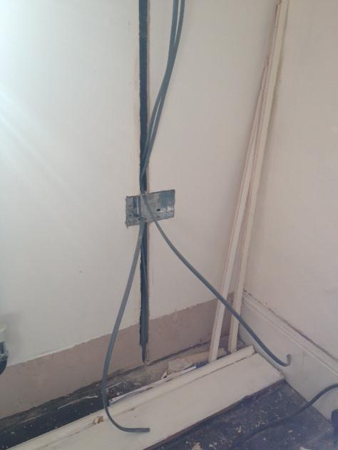
One of them is, yes - it's plasterboard approx 25mm from the solid brick wall. I'm using 35mm back boxes so the back box is embedded in the brick. The wires will be clipped to the brick also.

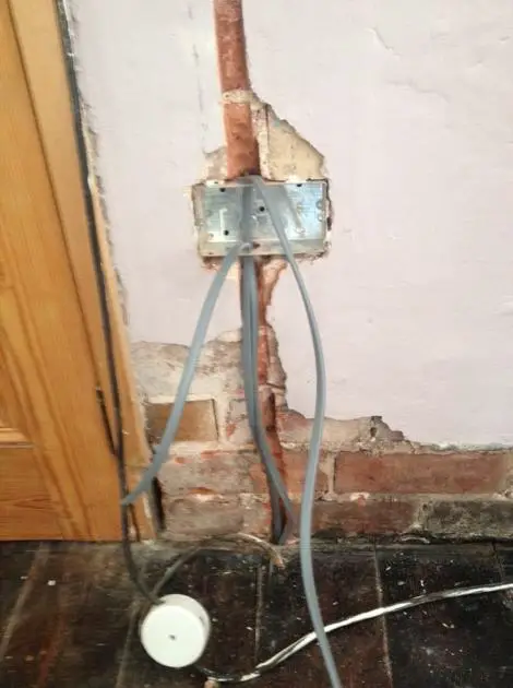
The other is 150yr-old rock hard render. Took me half an hour to make enough room for the back box. The bolster just wouldn't break the stuff.
 
What John has said is correct. You can have more than 44 meters using twin and earth 1.5 mm² it is up to you the designer to work out the design current. So if I take my house living room is 30W, dinning 48W, kitchen 120W bedrooms 20W so total is around the 350W mark so around 1.5A.

Sorry may have given local link before this one is the web site and if you enter 4.7 Ω as Zs and 1.5 mm² line and 1 mm² earth no for ring and 2 amp for design current you will gets around 137 meters. But Zs of 1.8 Ω and 6 amp design gives 44 meters both within 6.9 volt drop.

Working out the design current we use to use the On-site guide which from memory tells us to use 60W per fitting but clearly where the fitting will not take 60W one does not have to allow for it.

There is nothing to stop one using a ring with lighting or splitting lighting into groups but the British system is rose to rose not switch to switch which tends to reduce the volt drop.

The problem with some one else testing your work is your open to how they see the rules and some rules are not that easy to say exactly what they mean. As an example.

314.1 Every installation shall be divided into circuits, as necessary, to:
(iii) take account of danger that may arise from the failure of a single circuit such as a lighting circuit.

Now I have considered having an emergency light above the stairs means although my house which has a single lighting supply it is complaint. But where one relies on using lighting from sockets to ensure on a single MCB or RCD failure your not plunged into darkness then it's up to the inspector if he accepts under normal use the table lamp will be on.

Using all RCBO then there is clearly not a problem but using two RCD's is cheaper. So first step is design and ensure whole design is submitted so the council have to option to query anything they don't like before you install not after.

The two week time is between finishing a section and council inspection not sure it is two weeks but they have a time limit after which your allowed to proceed even if they have not inspected although you would be silly to do so. I see no problem the way you propose doing the work but doing room by room having to wait even one day before you can power up is a problem.

Councils do vary Liverpool were really helpful Flintshire were a real pain. I would guess the way you describe LABC fees around the £500 mark.

When my meters went for calibration I went to hire a set they wanted £75 for the minimum hire time of one week.

Some of the jobs my son got involved in took years and this caused them a problem as when he got divorced he stopped sole trading and went cards in and a condition of the employment was not to do any work on the side. He had a month to finish off all his work but that only works when the client was ready for him. There were a few unfinished jobs. This would be a problem for you with any one but LABC as people do stop trading and only the LABC can be relied on to be there on completion.

I really do wish you luck it is a large undertaking and the planning is the worse part. Look at a populated consumer unit 10 way at £50 and a RCBO at £20 so using RCBO's it £100 plus empty consumer unit at £24 I looked at Screwfix and BG brand for prices. Personally I would use RCBO's but it's your call.

This is repeated be it sockets or switches there are many options. I looked for two gang intermediate switches only some makers do them an if you want all to match then you have sometimes to use more expensive gear.

The how much to do is always a problem. I told my son he was going OTT with his house with a LAN connection at every radiator and it turned out I was right as he can't get hard wired TRV's so his switch in loft is not really required he will never need 100 hard wired LAN points and now the loft stairs are fitted the switch is not coming out of the loft. OK a little extreme but shows reason for planning.

Some things like two 32A radials to kitchen makes sense so may people want separate hob and oven. Others are a waste I installed cables ready for ring in my mothers house I now guess they will never be used.

Again good luck.
 
Sponsored Links
Is that plasterboard?!!

One of them is, yes - it's plasterboard approx 25mm from the solid brick wall. I'm using 35mm back boxes so the back box is embedded in the brick. The wires will be clipped to the brick also.

The other is 150yr-old rock hard render. Took me half an hour to make enough room for the back box. The bolster just wouldn't break the stuff.

Often with dot and dab walls you can find a hollow route to fish cables behind the plasterboard without causing all that devastation.

I would strongly recommend you use plastic oval conduit over those cables.

That way you have a chance of doing minor alterations or repairs in the future.

If you ever want to pull a little bit of slack in the future, you can if it's in tube.
 
What John has said is correct. You can have more than 44 meters using twin and earth 1.5 mm² it is up to you the designer to work out the design current. So if I take my house living room is 30W, dinning 48W, kitchen 120W bedrooms 20W so total is around the 350W mark so around 1.5A. ... if you enter 4.7 Ω as Zs and 1.5 mm² line and 1 mm² earth no for ring and 2 amp for design current you will gets around 137 meters. But Zs of 1.8 Ω and 6 amp design gives 44 meters both within 6.9 volt drop.
For those calculations, the Zs entered is obviously irrelevant, since the cable length one is calculating is limited by VD.

However, as BAS reminded us, it's not only the total design current which one has to determine, but also the distribution of that along the length of the circuit - which, as I said, makes calculation more complicated. However, to give you two examples of a total design current of 6A and a circuit length of 60m (roughly what the OP apparently has), wired in 1.5mm² cable:

(a) 10m to first lamp (1A load) and then 10m between each lamp (each one again a 1A load). With all lamps on, VD at furthest point of circuit is 6.09V (2.65%).

(b) 5m to first lamp (0.5A load) and then 5m between each lamp (each one again a 0.5A load). With all lamps on, VD at furthest point of circuit is 5.66V (2.46%).

Hence, with those distributed loads, both of those 60m circuits would be 'compliant' (max VD<3%) even with a total (distributed) load of 6A - although your calculation assuming that the entire 6A load was at the end of the circuit would indicate ('non-compliant') VDs appreciably greater than 3%, and that the maximum length for 'VD compliance' was about 44m.

Kind Regards, John
 
Whatever, I need not tell you that I'm personally pretty contemptuous about all this VD business.
Interesting. Is contempt your usual reaction to things for which you cannot see a reason? :eek:
No, if it's simply a matter of my not being able to 'see a reason' - since the most likely reason for that would be my own failings! In this case, although I obviously may still be wrong, it seems to me to be 'verging on the ridiculous'.

The only 'reason' I can think of is that 'they' wanted to be absolutely certain that the voltage supplied to a load on a lighting circuit could never be less than 209.3V (216.2V-6.9V) - but I do find it very hard to believe that such was their thinking.

I do accept that it's difficult to suggest how better it could/should have been done, given the potential degree of variation in supply voltage - but there surely has to be a 'better way' than what we have?

Anyway, this is all only 'my view/opinion', and I'm sure that others will disagree!

Kind Regards, John
 
Prefernottodieorburn.......

Can we see pictures of inside the socket please. :)
 
JohnW2 is again right to point out if lights are even spaced even with a 6A supply for working out volt drop you should consider it as 3A.

Also with for example GU10 LED lamps the voltage range given is often 150 - 250 volts and so in real terms volt drop is not a problem. The problem is if the inspector will accept it.

In the old days stone faced walls would have mineral insulated cable pushed into where mortar was removed and re-pointed when complete. That cable is not suitable for DIY it requires some degree of skill to use it. Today there is Ali-tube cable which is easier to use and similar to mineral insulated however unlike mineral insulated 2.5 mm² is still the minimum size with mineral insulated you could go down to 1.5 mm² I have not tried using the new cable in stone work and hesitate at talking about it but it may help where not hidden as like mineral cable it can be made to look neat you will have likely seem the orange version used on fire alarms in public buildings. The standard stuff for mains is white plastic coated.

You may also be better using maintenance free junction boxes under the floor and single instead of double drops in other words un-fused spurs. However it's back to the same old problem what the inspector will accept. We can suggest all sorts but it's not cut and dried how the regulations are read and if the inspector does not like it then it's a non starter.

As I have said before submit very detailed plans so once passed the inspector can't object it's already been passed. If the plans are very open then the inspector can object after he see it.
 
JohnW2 is again right to point out if lights are even spaced even with a 6A supply for working out volt drop you should consider it as 3A.
Strictly speaking, that is only exactly true if the load is truly 'uniformly distributed' along the entire length of the circuit - i.e. if there are an infinite number of infinitely small lamps. If one ones a precise answer for real-world situations, one has to work out th current, and hence VD, in each segment of the circuit (i.e. betwen lamps) and then add them up. In the examples I gave, the equivalent single load at the end of the circuit would be 3.5A in the first case (six 1A loads spaced with 10m between them) and 3.25A in the second case (twelve 0.5A loads spaced with 5m between them). The more lamps the load is spread across (along the entire length of the circuit), the closer does the 'effective current' get to 3A.
Also with for example GU10 LED lamps the voltage range given is often 150 - 250 volts and so in real terms volt drop is not a problem. The problem is if the inspector will accept it.
As you know, BS7671 requires only that the voltage supplied to the load should not be so low as to 'impair the safe functioning of the load'. The one problem you might conceivably have with an inspector is that (s)he might try arguing that one doesn't know what might subsequently be plugged into the lampholders - so that something far more voltage-sensitive might subsequently be plugged in. However, one would hope that common sense would prevail.

Kind Regards, John
 

DIYnot Local

Staff member

If you need to find a tradesperson to get your job done, please try our local search below, or if you are doing it yourself you can find suppliers local to you.

Select the supplier or trade you require, enter your location to begin your search.


Are you a trade or supplier? You can create your listing free at DIYnot Local

 
Status
Not open for further replies.
Sponsored Links
Back
Top