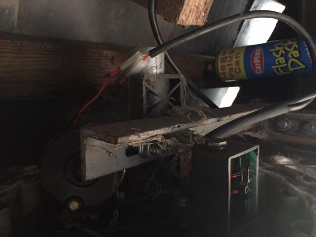
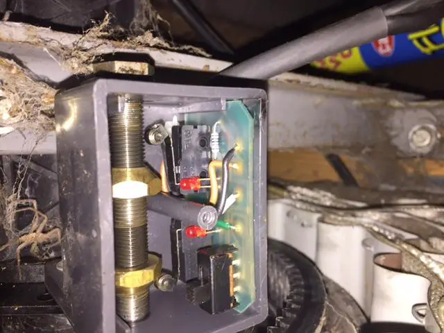
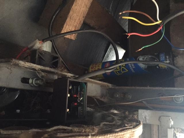
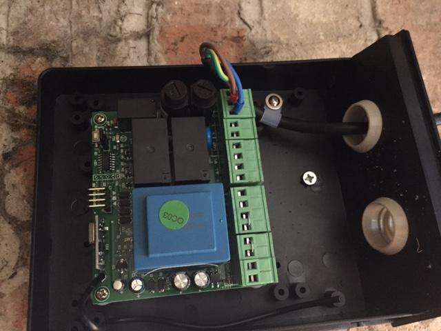
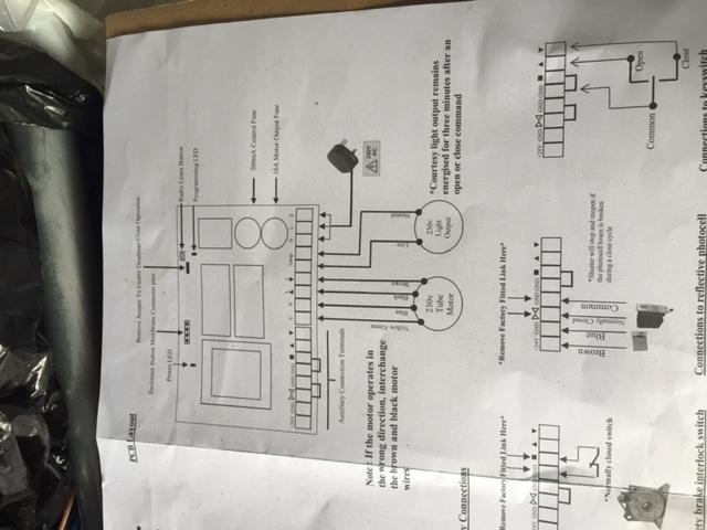
Hi, hoping someone can help me please. Have purchased a new control unit for our roller shutter. The new wiring diagram shows 5 cables coming from the motor but I have 6. Coming from the current control switch and motor are free,blue,red,yellow,brown,white. it looks like the yellow and red are connected directly to the motor and all other cores apart from the blue are going into some sort of control switch. There is no indication on any of the parts as to what each core/colour does. I have attached photos of the current control switch & motor along with the new control board and wiring diagram. Any help gratefully received. Thanks.