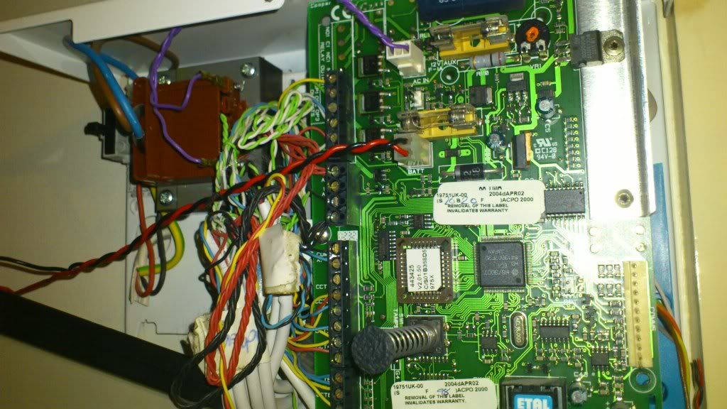
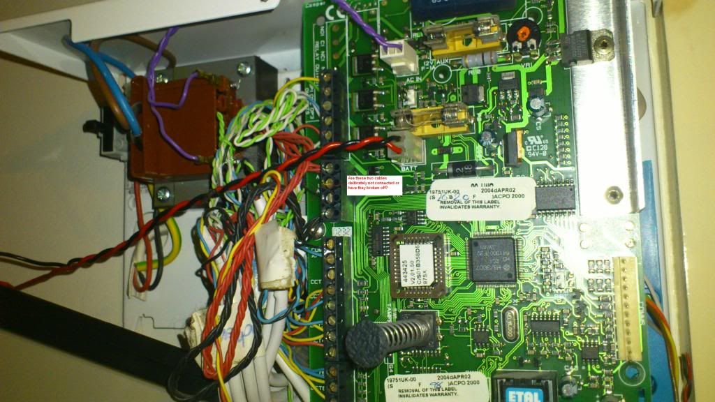
Currently I have a Scantronic 9751 Alarm system with 9930 LCD remote keypad. The software on the system is v02.01.
My problems started with the system showing Battery flt i.e. Missing battery and Unit battery Low power message. This was due to the battery being 10 years old . Anyway, I went into the installer mode and opened the control panel and replaced the battery unit - No issues in doing that. But when I tried to exit the installer mode by pressing 99, the system shows zone faults from 01-07. I have read the event log (using command 90), all it had was the Batt Flt Rstr (Battery restore) message. I did the walk test (command 97) and all the zones were tested no issues. I also ran Testing output command (i.e. 91, 92, 93, 94 and 95) and found no issues, although for 92 and 93 it didn't give any feedback so I assume its comms test which could be fine.
I did bit of a search on google and found that there is some issue with the software and power up and power down of the system should resolve it.
http://www.thesecurityinstaller.co.uk/community/topic/20536-scantronics-9751-zone-help/
I disconnected the battery and mains to see if that helps and it did not and I had issues with the system not accepting the installer code or the user code. So using the programming giude I performed a restore of the access code.
To restore all access codes to their default settings:
1. Remove mains power.
2. Open the case and disconnect the battery.
3. Identify the NVM Reset pins and Kick Start pins on the main PCB (refer
to the 9x5x Installation Guide).
4. Short circuit the NVM Reset pins with a wire link.
5. Short circuit the Kick Start pins with a wire link.
6. Reconnect the battery.
7. Remove the wire links from the NVM Reset pins and Kick Start pins.
The control unit will load the factory default access codes listed above.
8. Close the control unit.
9. Apply mains power.
10. Carry out an engineer reset (see next section).
Now the user code and installer code is reset and I was able to perform walk test (command 97) and testing output (command 91-95) - all ok no issues. But when I try to exit the installer mode (command 99) it gives out zone errors Z01- Z07! so I'm back to square one.
Any ideas how I can resolve the problem? I would really appreciate your thoughts and help!
PS: Apologies for the long post, I just wanted to make sure I have provided as much information as possible.
My problems started with the system showing Battery flt i.e. Missing battery and Unit battery Low power message. This was due to the battery being 10 years old
. Anyway, I went into the installer mode and opened the control panel and replaced the battery unit - No issues in doing that. But when I tried to exit the installer mode by pressing 99, the system shows zone faults from 01-07. I have read the event log (using command 90), all it had was the Batt Flt Rstr (Battery restore) message. I did the walk test (command 97) and all the zones were tested no issues. I also ran Testing output command (i.e. 91, 92, 93, 94 and 95) and found no issues, although for 92 and 93 it didn't give any feedback so I assume its comms test which could be fine.I did bit of a search on google and found that there is some issue with the software and power up and power down of the system should resolve it.
http://www.thesecurityinstaller.co.uk/community/topic/20536-scantronics-9751-zone-help/
I disconnected the battery and mains to see if that helps and it did not and I had issues with the system not accepting the installer code or the user code. So using the programming giude I performed a restore of the access code.
To restore all access codes to their default settings:
1. Remove mains power.
2. Open the case and disconnect the battery.
3. Identify the NVM Reset pins and Kick Start pins on the main PCB (refer
to the 9x5x Installation Guide).
4. Short circuit the NVM Reset pins with a wire link.
5. Short circuit the Kick Start pins with a wire link.
6. Reconnect the battery.
7. Remove the wire links from the NVM Reset pins and Kick Start pins.
The control unit will load the factory default access codes listed above.
8. Close the control unit.
9. Apply mains power.
10. Carry out an engineer reset (see next section).
Now the user code and installer code is reset and I was able to perform walk test (command 97) and testing output (command 91-95) - all ok no issues. But when I try to exit the installer mode (command 99) it gives out zone errors Z01- Z07! so I'm back to square one.
Any ideas how I can resolve the problem? I would really appreciate your thoughts and help!
PS: Apologies for the long post, I just wanted to make sure I have provided as much information as possible.