Hey guys,
I'm in the process of trying to wire up two lighting systems for my reptile tank with a timer to switch them on and off as needed throughout the day.
The first lighting system (Load A) runs through a 240vAC > 12vDC LED Driver which is then connected to a pair of red LED strips via a choc block.
The second lighting system (Load B) runs through an in-line 240vAC > 54vDC (no idea why it wants so high a voltage) transformer to an enclosed strip of white LEDs.
The timer is a TM-812M-2 twin channel digital programmable timer switch that I got from Amazon.*
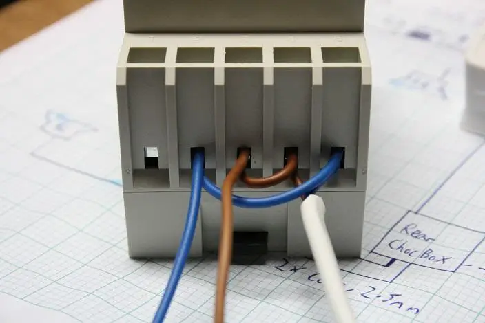
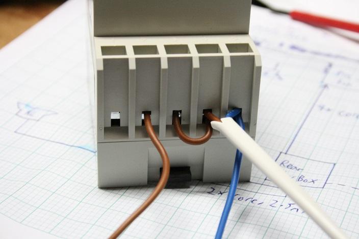
A plug was wired to the timer to provide it with a 240vAC input. Looking at the instruction sheet** for reference, the live wire has been connected to terminal 4. The neutral wire has been connected to terminal 5.
Load A has been connected to Channel A; the live wire to terminal 1 (Channel A: Normally Open) and the neutral wire to terminal 2 (Channel A: Common).
Load B has been connected to Channel B; the live wire to terminal 6 (Channel B: Normally Open) and the neutral wire to terminal 7 (Channel B: Common).
Now, my problem. I can confirm continuity between the various terminals is working as intended - when Channel A is switched 'On', there is continuity between terminals 1 and 2, and continuity between 2 and 3 when switched 'Off'. However, none of the connected equipment operates, and checking for voltage shows there is no voltage running through any of the output terminals.
I studied the leaflet again and found a sentence that I believe explains this; "This Timer provides Volt-Free output contact only." - I've googled Volt-Free output but don't really understand it, nor have I been able to find a guide for using it. Is this what the issue is? How do I get around it?
* http://www.amazon.co.uk/dp/B0077AX0US/ref=pe_385721_37038051_pe_217191_31005151_3p_M3T1_dp_1
** http://www.king-ielec.com.tw/all/manuals/timer/619mode_812m.pdf
I'm in the process of trying to wire up two lighting systems for my reptile tank with a timer to switch them on and off as needed throughout the day.
The first lighting system (Load A) runs through a 240vAC > 12vDC LED Driver which is then connected to a pair of red LED strips via a choc block.
The second lighting system (Load B) runs through an in-line 240vAC > 54vDC (no idea why it wants so high a voltage) transformer to an enclosed strip of white LEDs.
The timer is a TM-812M-2 twin channel digital programmable timer switch that I got from Amazon.*
A plug was wired to the timer to provide it with a 240vAC input. Looking at the instruction sheet** for reference, the live wire has been connected to terminal 4. The neutral wire has been connected to terminal 5.
Load A has been connected to Channel A; the live wire to terminal 1 (Channel A: Normally Open) and the neutral wire to terminal 2 (Channel A: Common).
Load B has been connected to Channel B; the live wire to terminal 6 (Channel B: Normally Open) and the neutral wire to terminal 7 (Channel B: Common).
Now, my problem. I can confirm continuity between the various terminals is working as intended - when Channel A is switched 'On', there is continuity between terminals 1 and 2, and continuity between 2 and 3 when switched 'Off'. However, none of the connected equipment operates, and checking for voltage shows there is no voltage running through any of the output terminals.
I studied the leaflet again and found a sentence that I believe explains this; "This Timer provides Volt-Free output contact only." - I've googled Volt-Free output but don't really understand it, nor have I been able to find a guide for using it. Is this what the issue is? How do I get around it?
* http://www.amazon.co.uk/dp/B0077AX0US/ref=pe_385721_37038051_pe_217191_31005151_3p_M3T1_dp_1
** http://www.king-ielec.com.tw/all/manuals/timer/619mode_812m.pdf
")