Thoughts on two circuits and two gang switch ?

Joined
4 Nov 2010
Messages
6,317
Reaction score
694
Location
Cumbria
Country
United Kingdom
I'm assisting a friend with some DIY, and before you get the flame throwers out, yes I know what is and isn't allowed by Part P.

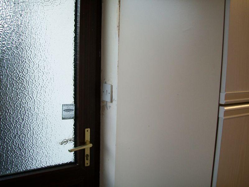
One thing he's asked me to help with is moving the (inside) switch for an outside light. It doesn't involved doing anything to the outside light or any outside wiring, just moving the inside switch. The most logical place for the switch is to be one half of a two gang switch - the other gang being the kitchen light. At present they are off the same way in the fuse box (yes it is a fuse box at the moment, but when he has that changed for a CU with RCBOs I'll be suggesting the outside lights are split off to a separate circuit.

What are people's thoughts in having the two switches in a two gang plate being on different circuits off the CU ?

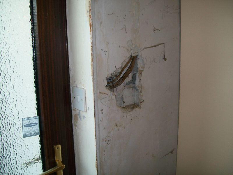
Incidentally, I found myself wondering "where do the cables run to that switch ?"


And then we moved the cabinet :roll:
 
What are people's thoughts in having the two switches in a two gang plate being on different circuits off the CU ?

Nothing wrong with that at all. It's found in many two-story houses which have two lighting circuits split as upstairs and downstairs, and a 2-gang switch operates the light in the downstairs hallway and the landing light upstairs.
 
And then we moved the cabinet
Can't make out what's going on - is that a curved, or triangular cabinet?
Sorry, it's not that clear.

In the first picture, you can see the large blank side of a tall cabinet, and just a small amount of it's doors. The cabinet side is more or less inline with the door surround where the light switch is located.

In the second picture, you can see the side of the next cabinet along, plus of course the butchery to the wall and wiring.
 
Nothing wrong with feeding a two gang switch from two different circuits each on their own RCBO.

It is very common for domestic hallways/landings.

In the commercial/industrial world you get grid switch plates with multiple circuits and often fed from multiple phases.
 
I found the pics quite illusional too. I couldn't understand how the hole suddenly appeared because of the angle of the first pic lol
 
Nothing wrong with feeding a two gang switch from two different circuits each on their own RCBO.

It is very common for domestic hallways/landings.

I would mark up the CU accordingly though, and put a laminated warning label inside the switch box.
 
Glad it just wasnt me then with the pics.
was wondering WTF was going on then :shock:
 
But more nice "sweeping" curves..................This bloke certainly gets about!
 
but worth leaving a clear note at the consumer uint to say which switch boxes have more than one MCB or RCBO supplying them.
That certainly makes sense, and one might argue its actually required (as part of 'identification'/documentation), but I wonder how often it's actually done, given that such a situation is presumably extremely common - quite probably more the rule than the eception for lighting switches in halls/landings etc.

Kind Regards, John.
 
That certainly makes sense, and one might argue its actually required (as part of 'identification'/documentation), but I wonder how often it's actually done, given that such a situation is presumably extremely common - quite probably more the rule than the eception for lighting switches in halls/landings etc.

QUOTE FROM THE ESSENTIAL GUIDE Document I1-9

Where an installation, item of equipment or an enclosure contains live parts that are not capable of being isolated by a single device† and no interlocking arrangement is provided to ensure that all the circuits concerned are isolated prior to gaining access, then Regulation 537.2.1.3 requires a durable warning notice to be provided.
The notice is required to be permanently fixed in such a position as to warn persons, prior to their gaining access, of the danger of live parts and the need to isolate using the appropriate isolating devices. The notice is additionally required, by Regulation 514.11.1, to indicate the location of each appropriate isolation device, unless there is no possibility of confusion. A typical example of such a warning notice is shown in Fig 3.
In some cases it may be necessary to consult a wiring diagram to determine how isolation is achieved. In such cases, reference to the appropriate drawing number(s) should be included on the warning notice.
It is important to note that the requirements of Regulations 537.2.1.3 and 514.11.1 are also applicable to Extra-Low Voltage (ELV) circuits.
 

If you need to find a tradesperson to get your job done, please try our local search below, or if you are doing it yourself you can find suppliers local to you.

Select the supplier or trade you require, enter your location to begin your search.


Are you a trade or supplier? You can create your listing free at DIYnot Local

 
Back
Top