Either do the job, or don't do the job, not work is completed until the paperwork is done.
So any electrical job can be split into three sections, the design, the installation, and the inspection and testing.
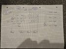
We start with the supply, we have three main types, TN, TT, and IT the latter rarely used. The TN is further split into two, we have TN-S and TN-C-S and with that type of supply, we look at the earth loop impedance, (ELI) and the prospective short circuit current, (PSCC) and the first is either measured or obtained line to earth, and the latter line to neutral, with a TN-C-S can use ohms law, so 230 V/0.35 Ω = 658 amps, and each circuit will have it's own readings, there are a number of reasons to work it out, one is a B16 MCB is two devices in one, at over 16 amp in the fullness of time, it will trip, using the thermal part of the trip, but not fast enough to comply with regulations, the B means the it will trip between 3 and 5 times the thermal rating, on the magnetic part of the trip, which trips very fast, so we work on the times 5 plus 5% to allow for volt drop, so looking for a loop impedance of 2.73 Ω both line - neutral and line earth unless a TT supply then only line - neutral, the same reading will also allow the calculation of volt drop.
This is a bit more complicated, using the 0.35 Ω for incoming looking at 1.29 Ω at the end of the B16 circuit line - neutral to be within the volt drop, this equates to around 24.7 meters of 1.5 mm² cable, yes we can work it out before we ever start work.
However since we likely have many circuits, one which may feed off another, we tend to make a mental judgement, will it be near the limit, and if not, install then test. This can go wrong, I remember installing a 4 mm² circuit, and having to redo it in 10 mm² as volt drop resulted in shrink wrap machine not working, and trying to hide the error from the bosses. (Not my error, I had said before we started I thought it was too long of a run)
Your plan does not show any lengths, or the supply paramours, so I could not work it out even if I wanted to. But I am not the designer, and am not signing the paperwork as such.
The design is not only electrical, there are also other regulations to consider, and some we often flaunt with domestic, one example is the 0.37 kW rule is an example, so at work the bench grinder if power is lost, since over a 370 watt motor, must disconnect, so when power is returned it does not start up again, called a no volt release, but for domestic use, bench grinders often have just a flick switch.
I use to fit an active RCD to the grinder supply, cheaper than the proper starter, and to be frank not sure if that complied with HSE rules, but was never picked up on it.
Leaving design, installation also has some rules, and they can change depending if you can see the cables or not. I have had heated arguments over SWA v Steel conduit, and how often you need to place saddles. Even how many stainless steel tie wraps per plastic are required under fire regulations. Remember you are wiring a garage, so fire has to be considered.
I see no problem in using semi-skilled labour, however the law does not agree, the Emma Shaw case put into question the use of electricians mates. However for an electrician to design an installation, and then use semi-skilled to do the installation, and then return for the inspection and testing seems OK to my mind, but to design by groups on the internet is not the way to go, I have given advice at work, and latter gone to visit, and the guy has proudly shown me his work, and I am thinking when I said xyz I did not think you were doing that.
To an electrician 230 volt is low voltage, unless American, 12 volt is extra low voltage, this is ISO rules, but many DIY think 12 volt is low voltage, so it is very easy to give wrong info, simply down to use of English, it needs a site visit, not a forum to work out what you need. And for the designer to have insurance to cover him should he made an error.