- Joined
- 24 Feb 2020
- Messages
- 17
- Reaction score
- 0
- Country

After living in my house for 20 years I thought it might be a good idea to have a closer look at the pipework in the central heating system. Yes I know 
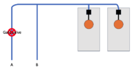
I’ve got an old school system with two tanks in the loft. Most of the pipework makes sense to me, apart from the supply of mains water to the two ballcocks, one in each tank.
So there are two pipes coming up from the ground floor, one of which has a gate valve. They join together and then separate before feeding the ballcocks.
The gate valve doesn't turn so I don’t know if it’s stuck in the open or shut position, however…
If I empty some water from a tank and the ballcock activates, then pipe B gets cold so I know water is flowing through it.
Anybody know why the ballcocks would be supplied like this?
Many thanks for any inspiration!
Pathetic diagram attached for your amusement and criticism.