shorting coils on an alternator

Joined
24 Nov 2004
Messages
465
Reaction score
7
Country
United Kingdom
Pls excuse this posting which is somewhat off topic but purposeful to tap into a community without "accepted" bike-lore opinions. I am a stranger to the world of vintage bikes. An uncle who has become recently into nice old British bikes has asked me about wiring and converting alternators from the stock 6V systems to current 12V systems.
A lot of the theory appears to involve bunching the 3 phases coming out of the alternator together into one conductor and then feeding that lot to a rectifier/regulator unit....., against the "Common" point from the alternator (which I guess is the centre of a star wound coil arrangement) - as shown here:
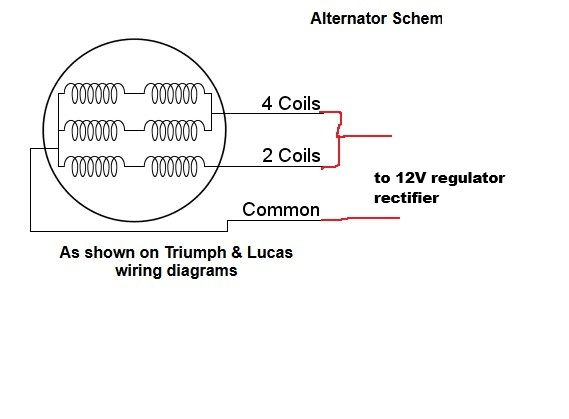
BSA latest 12V technique.png

present "modification" advice being as I have indicated with red pen. This strikes me as "Not Right" because it basically appears to short the 3 phases at the alternator. My limited practical experience of alternators is with small simple chinese wind-turbines, where the mfg-advised method of "braking" the fan is to short the 3 phases, which kills the output and puts max load on the fan in an attempt to stop it. If the wind power overloads this torque then the alternator cooks up, presumably because ALL the current from the peaking winding gets forced through its neighbours, many times a second.

perhaps I am missing nuance in the way that an alternator can be arranged?

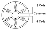
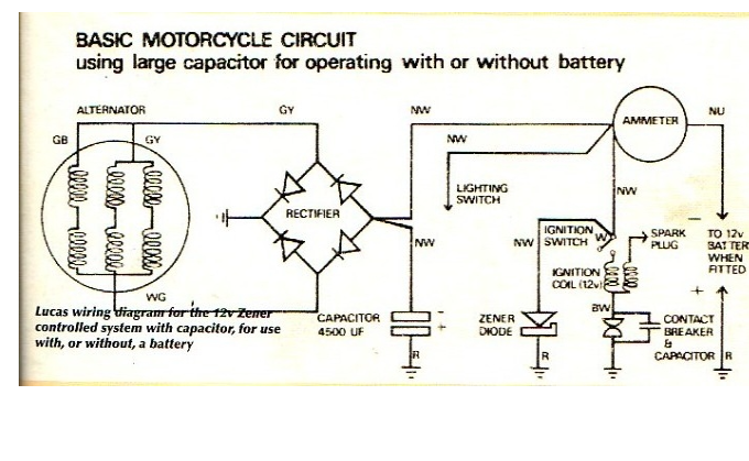
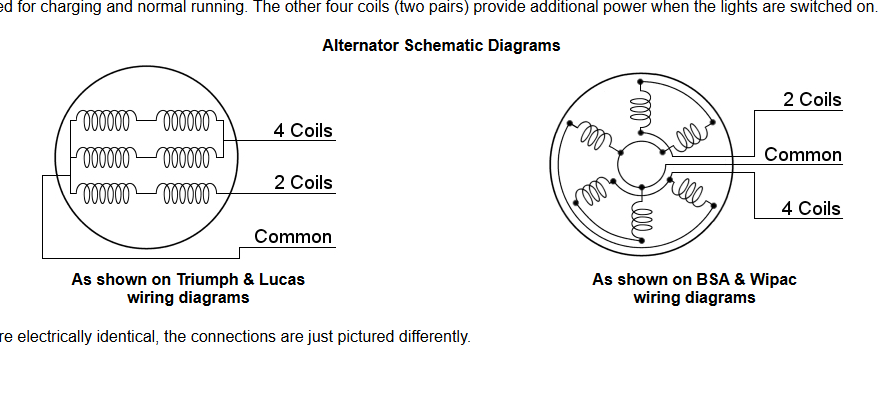
there are stock drawings from the original bike manuals that indicate sets of coils can be shorted together, see here:
generic motorcycle alternator diagram.png

bsa_triumph_diagrams.png


None of this seems right to me but I must be missing something. I just wondered whether the original stock "kludge" of shorting together the 2 pairs of windings was a known trick, then latterly the biking community has (with some ignorance?) blindly extended that trick to shorting all 3 coils together?
I must be misunderstanding sthgh because if this was genuinely an error there would be fried alternators all over the place.
 

Attachments

  • generic motorcycle alternator diagram.png
    generic motorcycle alternator diagram.png
    377.8 KB · Views: 12
Each flywheel generator seemed to have its own wiring, I remember back in the 70s trying to convert to 12 volt, and to add extras to the system, and it not only depends on the coil arrangement but also the magnets, there was basic no standard between motor bikes.

The one I had there were 5 coils, the sixth place had the contact breaker for the ignition, and each coil had different gauge wire, and different number of turns, so one coil for side lights, two coils for headlights, one coil for stop lights, one for the horn, and one for ignition.

But another bike had 6 coils, and a magneto, as you show here, 1785751200136.png with the common not using the frame, we would take the common to the centre of the two batteries, and half wave pos to one battery and neg to the other, and a zenor diode across the battery to stop over charging.

But things have moved on, so today we have LED lights etc, and also switch mode power supplies which can convert nearly anything to anything, so I am sure there are devices now made which make it all easy.

I would look for a bike forum, and see what is made. Some things seem daft, my e-bike as a great headlamp but not tail lamp, I have to use a lamp clipped on at the back with its own batteries, but it comes from the 48 volt traction battery at the front.

So at what point it is simply easier to have a battery charged each day just for lights, the new batteries are so light, is it worth all the messing around to get good lights from the alternator?

Either way is not standard, so its down to what is easy.
 
I guess in essence I am wondering in what situation it is "good practice" to short the coils on a generator?
I seem to be thinking of it as short-circuiting a current source: one would never join together 2 of the three phases at a 400V mains supply just to get a higher current for a singlephase purpose.

in the case of the cheap chinese windmill system, I am not surprised, you get what you pay for: the theory (I suppose) is that in shorting the alternator the load on the fan is massively increased so there is a natural braking effect. however, when the wind power exceeds the braking power then the coils cook up. the chinese windmill probably specifies "do not use in winds above 5m/s"

this theory (weak as it is) does not transfer to the case of the motorbike because the petrol engine will always spin the alternator possibly into destruction.
 
On the Falklands we had two small generators to power floodlights, one was around 3 kVA and the other 6 kVA one with a single cylinder lister the other with a twin cylinder lister, and they looked the same, except one larger to the other, but in fact the 3 kVA could burn its self out, but the 6 kVA could not, if you overloaded the 6 kVA the field of the generator collapsed, and it could not be overloaded. Yet both of the same basic design.

We also had some 12 kVA with 12 windings, which could be arranged to give single phase or three-phase, and also different voltages. Single phase was called zigzag wiring.

Shorting out a winding may be OK, as at zero volts it may be also zero amps, but it would depend on internal resistance of the coils, and there is no real way to know. A lot depends on cooling as well.

So if the field of a generator is on the outside, and the generating part on the inside, there is less cooling surface to doing the reverse, which is why we moved from the dynamo to alternator in the car, and in the car, most could not produce enough amps to damage the windings. However not all vehicle alternators were like that, the ones designed for buses needed a high output at tick over, and the CAV AC 208 had a special 440 regulators with M1 and M2 terminals which went across a resistor to measure the output, and that alternator had current as well as voltage regulation.

There were so many alternators made, some were brushless, so even had a three-phase transformer built in and had a 12 and 24 volt output.

The French did a cheap single phase version with half-wave rectifiers, and the list goes on.

I had an outboard engine with electric start, which had no way to recharge the battery, you simply charged the battery at home.

So I look at my e-bike today, with a 48 volt battery, and one has to ask, at the size of modern batteries does it really need to be recharged by the motorbike?
 
Pls excuse this posting which is somewhat off topic but purposeful to tap into a community without "accepted" bike-lore opinions. I am a stranger to the world of vintage bikes. An uncle who has become recently into nice old British bikes has asked me about wiring and converting alternators from the stock 6V systems to current 12V systems.
A lot of the theory appears to involve bunching the 3 phases coming out of the alternator together into one conductor and then feeding that lot to a rectifier/regulator unit....., against the "Common" point from the alternator (which I guess is the centre of a star wound coil arrangement) - as shown here:View attachment 419754
present "modification" advice being as I have indicated with red pen. This strikes me as "Not Right" because it basically appears to short the 3 phases at the alternator. My limited practical experience of alternators is with small simple chinese wind-turbines, where the mfg-advised method of "braking" the fan is to short the 3 phases, which kills the output and puts max load on the fan in an attempt to stop it. If the wind power overloads this torque then the alternator cooks up, presumably because ALL the current from the peaking winding gets forced through its neighbours, many times a second.

perhaps I am missing nuance in the way that an alternator can be arranged?slope game

there are stock drawings from the original bike manuals that indicate sets of coils can be shorted together, see here:

View attachment 419758
View attachment 419759

None of this seems right to me but I must be missing something. I just wondered whether the original stock "kludge" of shorting together the 2 pairs of windings was a known trick, then latterly the biking community has (with some ignorance?) blindly extended that trick to shorting all 3 coils together?
I must be misunderstanding sthgh because if this was genuinely an error there would be fried alternators all over the place.
could I use the method of connecting the three phases together into one conductor for the rectifier/regulator unit, or is there a more appropriate technique that preserves the integrity of the alternator's output?
 
The method used in old British motorbikes was to use a coil for each job. Often each coil had a different gauge of wire. But some did charge a battery, often 6 volts, and it was really a bit of hit-and-miss, and it was a regular job to put the battery on charge.

So the headlight switch as well as turning on the headlight, would switch in or out more or less coils.

If the coils at 60º to each other, and you have two magnets, you would get three-phase, however often there were many more magnets, so the coil outputs could be in phase with each other.

Even with the early car alternators, some were still single phase, Paris Rhone for example, two windings and both half-wave rectified, so in real terms there was no standard method used.

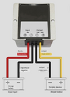
I am sure it would be possible to use some form of rectification to get 12 volts, basic one battery charged off one half cycle, and the other off the other half cycle, with the common being the centre point between the batteries. Today this 10 amp unit can do it for us, 1786970379309.png but Input voltage: DC 6V (5V-11V) but output is 12 volts, and really you want 13.8 volt, and the question has to be, would you trust this unit not to fail?

I remember a Bedford van with a voltage overload rather than a fuse, on the headlights, and it tripped, and I was left to pray, lucky it reset before I hit anything, but this is why we would use a separate fuse high and low beam or left to right, so if the fuse ruptured you could flick to other beam, or if two headlights one would stay on.

There are battery to battery chargers, Sterling do one for narrow boats, designed to charge a battery in the bow for the bow thruster, but one it is 12 volt to 12 volt, and two in a narrow boat weight does not really matter.

So as it stands, I do not know of a ready built unit to do the job, there is no technical reason not to make one, but a google hunt tells us anything using 6 volt is rare.

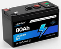
So with a vintage motorcycle, the question has to be, will the effort to convert 6 to 12 volts be worth it? So this 1786971978497.pngweighs 1.5 kg and 80 Ah should last a day with no problem. As to a smaller version now we start to look at the head lamp. There are rules as to using LED head lamp bulbs, and I don't know what they are.

However, the big question, with a vintage motorcycle, at what point does one say stop? How far can one alter something before it is no longer vintage? Go to Beamish Museum, and they have a compressor hidden in the engine tender to work the air brakes. You really need to look hard to find the air brake controls etc, but it is needed for safety.

So we do have to move from standard sometimes, but to put an EV power unit in a Moris Minor to my mind is going too far.

So if I had a vintage motorcycle it would only have 6 volt lighting, and I would only use it in an emergancy.
 

If you need to find a tradesperson to get your job done, please try our local search below, or if you are doing it yourself you can find suppliers local to you.

Select the supplier or trade you require, enter your location to begin your search.


Are you a trade or supplier? You can create your listing free at DIYnot Local

 
Back
Top