- Joined
- 24 Nov 2004
- Messages
- 465
- Reaction score
- 7
- Country

Pls excuse this posting which is somewhat off topic but purposeful to tap into a community without "accepted" bike-lore opinions. I am a stranger to the world of vintage bikes. An uncle who has become recently into nice old British bikes has asked me about wiring and converting alternators from the stock 6V systems to current 12V systems.
A lot of the theory appears to involve bunching the 3 phases coming out of the alternator together into one conductor and then feeding that lot to a rectifier/regulator unit....., against the "Common" point from the alternator (which I guess is the centre of a star wound coil arrangement) - as shown here:
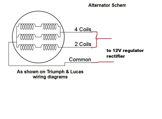
present "modification" advice being as I have indicated with red pen. This strikes me as "Not Right" because it basically appears to short the 3 phases at the alternator. My limited practical experience of alternators is with small simple chinese wind-turbines, where the mfg-advised method of "braking" the fan is to short the 3 phases, which kills the output and puts max load on the fan in an attempt to stop it. If the wind power overloads this torque then the alternator cooks up, presumably because ALL the current from the peaking winding gets forced through its neighbours, many times a second.
perhaps I am missing nuance in the way that an alternator can be arranged?
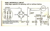
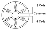
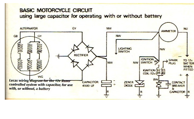
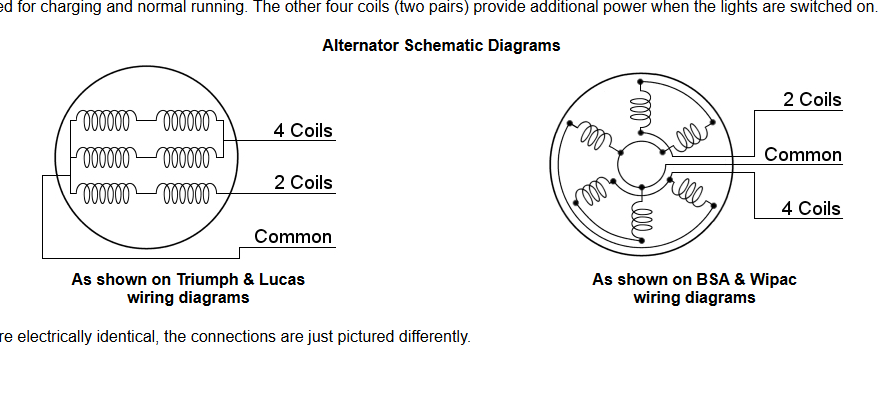
there are stock drawings from the original bike manuals that indicate sets of coils can be shorted together, see here:
None of this seems right to me but I must be missing something. I just wondered whether the original stock "kludge" of shorting together the 2 pairs of windings was a known trick, then latterly the biking community has (with some ignorance?) blindly extended that trick to shorting all 3 coils together?
I must be misunderstanding sthgh because if this was genuinely an error there would be fried alternators all over the place.
A lot of the theory appears to involve bunching the 3 phases coming out of the alternator together into one conductor and then feeding that lot to a rectifier/regulator unit....., against the "Common" point from the alternator (which I guess is the centre of a star wound coil arrangement) - as shown here:
present "modification" advice being as I have indicated with red pen. This strikes me as "Not Right" because it basically appears to short the 3 phases at the alternator. My limited practical experience of alternators is with small simple chinese wind-turbines, where the mfg-advised method of "braking" the fan is to short the 3 phases, which kills the output and puts max load on the fan in an attempt to stop it. If the wind power overloads this torque then the alternator cooks up, presumably because ALL the current from the peaking winding gets forced through its neighbours, many times a second.
perhaps I am missing nuance in the way that an alternator can be arranged?
there are stock drawings from the original bike manuals that indicate sets of coils can be shorted together, see here:
None of this seems right to me but I must be missing something. I just wondered whether the original stock "kludge" of shorting together the 2 pairs of windings was a known trick, then latterly the biking community has (with some ignorance?) blindly extended that trick to shorting all 3 coils together?
I must be misunderstanding sthgh because if this was genuinely an error there would be fried alternators all over the place.