Hello gents
I would appreciate advice on this please.
I have three single blanking plates behind where a cupboard used to stand.
My plan was remove the blanking plates and attach new wall plates to each box.
This is what was behind each plate:
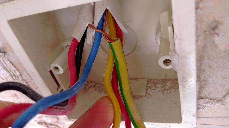
Box 1 has 2 earth wires, 2 red wires, 1 black wire, 1 blue wire and 1 yellow wire.
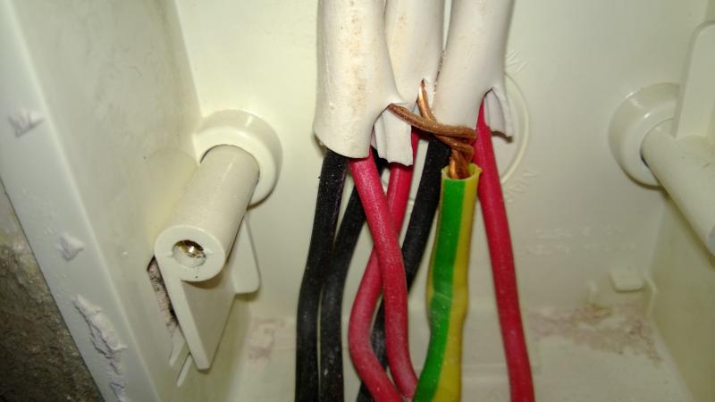
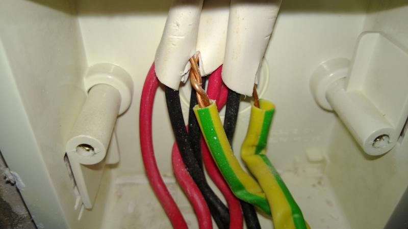
Box 2: 3 black, 3 red, 3 earth.
Box 3: 3 black, 3 red, 3 earth.
Boxes 2 & 3 I think are straight forward enough but what should be done with box 1?
Thanks in advance for any kind help.
Cheers.
I would appreciate advice on this please.
I have three single blanking plates behind where a cupboard used to stand.
My plan was remove the blanking plates and attach new wall plates to each box.
This is what was behind each plate:

Box 1 has 2 earth wires, 2 red wires, 1 black wire, 1 blue wire and 1 yellow wire.
Box 2: 3 black, 3 red, 3 earth.
Box 3: 3 black, 3 red, 3 earth.
Boxes 2 & 3 I think are straight forward enough but what should be done with box 1?
Thanks in advance for any kind help.
Cheers.