
You are using an out of date browser. It may not display this or other websites correctly.
You should upgrade or use an alternative browser.
You should upgrade or use an alternative browser.
Add room stat to system
- Thread starter bottle top
- Start date

Thanks+sorry
I was editing my last post while you replied.
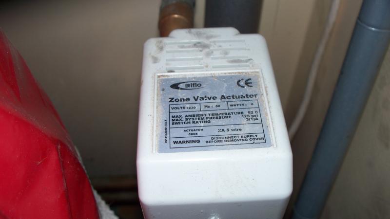
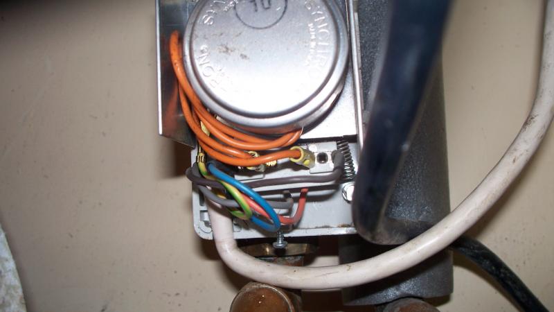
HW ZV is IFLO ZA5. I can just make out cut back orange and grey wires enoughto do continuity test when valve is actuated and microswitch works.
Ch ZV fails on continuity when actuated.
The red wire in the above pics is in fact orange.
Would not want to remove whole valve so can microswitch be replaced or can I use separate relay for switching.
Thanks again.
I was editing my last post while you replied.
HW ZV is IFLO ZA5. I can just make out cut back orange and grey wires enoughto do continuity test when valve is actuated and microswitch works.
Ch ZV fails on continuity when actuated.
The red wire in the above pics is in fact orange.
Would not want to remove whole valve so can microswitch be replaced or can I use separate relay for switching.
Thanks again.
Thanks doit all.
Space saver 80 mk 2
Space saver 80 mk 2
Thanks
Yes. On the pull down panel that exposes thermostat it says space saver 80 mk2, but on the instructions on the panel for lighting the pilot light it just says space saver mk2
Yes. On the pull down panel that exposes thermostat it says space saver 80 mk2, but on the instructions on the panel for lighting the pilot light it just says space saver mk2
Iflo valves are Drayton's rebadged for Travis Perkins.
If you look carefully it says "ZA 5 wire", which, I assume, means that it has five wires.
The only reason, I can think of, for such a strange wiring is that the auxiliary switch in the valve actuator is faulty and this is a get around.
If the existing actuator has gone belly up, you may be able to replace it, without buying the complete valve. The equivalent Drayton actuator will fit.
Ok
So I need to drain down system, replace CH valve ( can not remove acuator ) and rewire, refill, inhib, wire in roomstat,etc.
I feel confident enough to do this after everyones help so thank you to all.
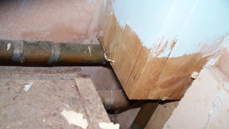
One thing still bugging me though. What if the system is plumbed in such a way that I can not get independent control. I have looked at the boiler and can only see three pipes gas, water in, water out?. see pic.
Looking at the s plan pipe layout there are 3 water pipes connected to boiler.
Could it be that the feed for the cylinder is taken off the CH feed ie in parrallel??
So I need to drain down system, replace CH valve ( can not remove acuator ) and rewire, refill, inhib, wire in roomstat,etc.
I feel confident enough to do this after everyones help so thank you to all.
One thing still bugging me though. What if the system is plumbed in such a way that I can not get independent control. I have looked at the boiler and can only see three pipes gas, water in, water out?. see pic.
Looking at the s plan pipe layout there are 3 water pipes connected to boiler.
Could it be that the feed for the cylinder is taken off the CH feed ie in parrallel??
Don't know what S Plan layout you have been looking at, but this one is from Honeywell and only show two pipes (excluding gas).
View media item 71
The flow pipe divided in two after the pump. One branch goes, via a motorized valve to the radiators; the other branch, via a second MV to the hot water cylinder.
View media item 71
The flow pipe divided in two after the pump. One branch goes, via a motorized valve to the radiators; the other branch, via a second MV to the hot water cylinder.
Sorry I am missing something here, I was looking at the same plan. I can see three pipes leaving the boiler two cold ( blue ) and one hot ( red ).
Incidently in my system the pump is next to the HW cylinder and is fed by the expansion tank in the attic ( I think, pipe certainly goes into the attic where tank is ). The pump then feeds the two MVs which T off to HW and CH.
Incidently in my system the pump is next to the HW cylinder and is fed by the expansion tank in the attic ( I think, pipe certainly goes into the attic where tank is ). The pump then feeds the two MVs which T off to HW and CH.
OK, I did miss that (familiarity etc). It's just the way the system has been drawn. The blue pipes are returns. In real life, the cylinder return (left one) is connected into the heating return; so only one pipe actually goes to the boiler.Sorry I am missing something here, I was looking at the same plan. I can see three pipes leaving the boiler two cold ( blue ) and one hot ( red ).
That's quite normal. The 15mm cold water fed from the expansion tank feeds into the flow from the boiler just before the pump. You may also find a second 22mm pipe, about 150mm from the feed pipe. This is the vent pipe which hangs over the expansion tank. Some systems combine the feed and vent pipe, if so it will be 22mm.Incidently in my system the pump is next to the HW cylinder and is fed by the expansion tank in the attic ( I think, pipe certainly goes into the attic where tank is ). The pump then feeds the two MVs which T off to HW and CH.
Thanks for clearing that up.
Will let you know how I got on but might not be for a couple of weeks yet.
Cheers
Will let you know how I got on but might not be for a couple of weeks yet.
Cheers
Please post back to this topic. Then we won't have to scrach our heads wondering what you are talking about.Will let you know how I got on but might not be for a couple of weeks yet.

Success.
Fitted the new ZA5 zone valve on friday and did the S plan wiring on monday with the new room stat and a wiring centre. Everthing works fine, HW and CH controlled by cylinder stat and room stat respectively so boiler and pump actually switch off once stats are satisfied which was not the case before.
As suggested put room stat in living room and put trv on full.
Just need to add inhibitor to system.
Just one more question. bearing in mind I have a glow worm space saver 80 mk 2 and and a room stat and cylinder stat what is the best setting for boiler thermostat. I have read in other posts the best setting is max but not 100% sure why.
DIYnot Local
Staff member
If you need to find a tradesperson to get your job done, please try our local search below, or if you are doing it yourself you can find suppliers local to you.
Select the supplier or trade you require, enter your location to begin your search.
Please select a service and enter a location to continue...
Are you a trade or supplier? You can create your listing free at DIYnot Local
Similar threads
- Replies
- 11
- Views
- 2K
- Replies
- 1
- Views
- 692
- Replies
- 8
- Views
- 2K
- Replies
- 18
- Views
- 10K