Hi all,
I currently have no room thermostat attached to my ferroli combi boiler, out of 11 rads there are 8 that have TRVs fitted.
Firstly are the wireless devices reliable?
I have the Ferroli manual and the Honeywell installation manual, its seems fairly straight forward fitting the thermostat, but is the Honeywell compatible with the boiler and if so could someone with that bit of knowledge of Ferroli boilers explain the best way of doing things.
The current set up is the boiler has a 3amp fused plug to power it, I assume I would need to T off this supply to run the honeywell receiver, it mentions in the ferroli manual that the connections on the board for the thermostat are voltage free.
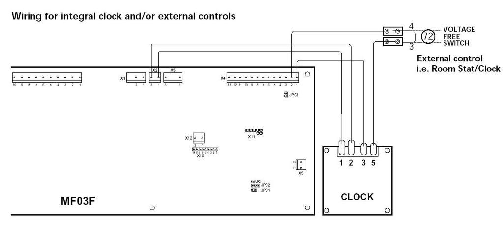
Note - When connecting a room thermostat or external timer, do not link the power supply of these devices to the
switching contacts. The switch contacts must be voltage free. Any mains powered devices must utilise mains power
solely to drive the timer motor.
Can someone explain this little bit for me.
IT currently has a built in timer on the front panel I assume this could just be left on 24hrs and leave the honeywell do the switching on and off as needed.
Thanks in advance for any help
A.S
I currently have no room thermostat attached to my ferroli combi boiler, out of 11 rads there are 8 that have TRVs fitted.
Firstly are the wireless devices reliable?
I have the Ferroli manual and the Honeywell installation manual, its seems fairly straight forward fitting the thermostat, but is the Honeywell compatible with the boiler and if so could someone with that bit of knowledge of Ferroli boilers explain the best way of doing things.
The current set up is the boiler has a 3amp fused plug to power it, I assume I would need to T off this supply to run the honeywell receiver, it mentions in the ferroli manual that the connections on the board for the thermostat are voltage free.
Note - When connecting a room thermostat or external timer, do not link the power supply of these devices to the
switching contacts. The switch contacts must be voltage free. Any mains powered devices must utilise mains power
solely to drive the timer motor.
Can someone explain this little bit for me.
IT currently has a built in timer on the front panel I assume this could just be left on 24hrs and leave the honeywell do the switching on and off as needed.
Thanks in advance for any help
A.S