Battery Charging Narrow boat

Joined
27 Jan 2008
Messages
23,630
Reaction score
2,662
Location
Llanfair Caereinion, Nr Welshpool
Country
United Kingdom
To the left is a simple picture of how the batteries could be charged. Switch J1 will change the supply to battery charger from Shore power to inverter it could be a relay energised by the shore power.

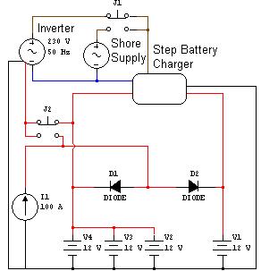
The switch J2 changes the inverter supply from the alternator to the domestic batteries this I am not sure on as I don't know how the inverter will handle the rectified 3 phase supply? A fourth small battery less than 20Ah may be required to smooth supply to inverter? Again the switch could be a relay energised by the alternator output.

The idea is that when the alternator is running any power over and above what the inverter requires will be supplied direct to batteries in normal manor. So after starting the batteries will charge as normal. However once the current starts to drop to under 25A then the Step Battery charger should raise the three domestic batteries voltage to 14.4/14.8V according to DIP switch setting until the current drops to 2.5A or 4/8 hours has elapsed according to DIP switch setting.

If this system will work the only item, which needs buying, is the inverter. The main idea is to reduce the charge time so with deep discharged batteries in the morning they are likely to be charged by the evening when the main engine is finished with.

It looks so simple I worry I have missed something. Any comments welcome.
Eric
 
Sponsored Links
Not sure on only having 1 pole switching on the 230v side, to me it would need to be at least double poled with some interlocking to ensure that you cannot feed back into the catenary cable to the shore.
Be extrememly careful when designing a relay system for switching between two mains system also, I have seen quite a few designs which can latch!
Would it be easier to bolt another alternator onto the side of the engine, play about with the excitation voltages etc to up the charge?
 
why start a second post? you could have tacked this on the end of the other post..

you havent told us what all the parts in your drawing are..
 
Likely he will use an isolation transformer and yes most likely would use double pole switching. It is a rough diagram to find if the principle is sound or not. Seems so simple I am sure I have missed something.
 
Sponsored Links
why start a second post? you could have tacked this on the end of the other post..

you havent told us what all the parts in your drawing are..
I have modified my ideas a lot. This is a much simpler method and cheaper.
Circle with arrow is engine alternator 100A the Diodes are one unit blocking diode designed to take 100A the step battery charger is a MOBITRONIC automatic double charger, 25 A, 12 V - Ref. No. 925-012TB as yet have not got an inverter it would need to be at least 500VA more likely 2.5kva sine wave output. Shore supply at moment TT but soon will use isolation transformer so will be TN-S all three batteries are 160AH I think absorbent glass mat lead acid leisure / traction batteries. The switches don't know what I will use as I said may use relays.

It is the principle I am looking at I will modify slightly I am sure. One item I am still worried about is battery sizes they are too big. The MOBITRONIC automatic double charger is only designed for 300Ah and I worry if the charge rate will drop below the 10% or 2.5A required for it to drop out of the rapid charge mode. There is a timer which can be set with DIP switches to limit it to 4 or 8 hours. Using a current sensor and only starting the charger once the alternators output has dropped below 25A is also an option.

But to start with I am trying to keep it simple.
 
ok so to get this straigh in my head...

with the engine running, you want the alternator to directly charge the batteries...

then, once the charging current falls below 25A, you want the step charger to kick in and "boost / fast" charge your batteries, using the alternator to power the inverter to power the charger?

you do know about the diodes dropping 0.6 ish volts from the alternator voltage? you need to maintain at least 13.8V at the batteries to charge..
 
Does the alternator need a 12v "Excitation" supply to start working?
 
I do realise about the 0.6 volt drop and the diodes already exist so I assume the alternator has it's output set at 14.4 volts to compensate although as yet unmeasured.

I was many years ago an auto electrician but for last 20 years I have worked on low voltage and PLC's so I am a little outdated.

It seems a good idea so why is it not used on every narrow boat? So with that in mind I wonder if I have missed something?

Inverter prices have fallen over the years and it may be until recently the inverter cost stopped this approach?

Also if he had not already got a switch mode step charger there are units which will do this direct from engine alternator which also have little extra features like temperature senders on batteries and alternator.

Eric
 
http://www.power-store.com/view-item.asp?itemid=1142&search=vsr&
I had looked at these units but it will not allow two batteries to be charged at different voltages. For engine battery it only requires a float charge at 13.8 volts however the domestic batteries need a step charge starting at 14.8 volts there are special regulators which can boost the alternators output to 14.8 volts or with diode 15.4 volts but that means the engine battery is over charged.

However there is some good stuff on same site and I am still looking through it all. We see a problem with existing charger from mains as it drops out of the 14.8V step when the current drops to 2.5A which means any equipment that is used on board will prevent it ending the stage at the correct time. There is also a timer which can be set to 4 or 8 hours but still thinking of methods to supply the domestic while on shore power without drawing on charger.
 
If you need 2 different systems is it viable to run 2 separate alternators?
 
If you need 2 different systems is it viable to run 2 separate alternators?
I have considered it but from looks of engine it will not be easy and one of the alternators would need altering anyway to give stage charging so far more expensive than one of these at around the £300 mark. The inverter will be required anyway so the method I show will cost very little.

I want to sit down with my son and prospective daughter-in-law and talk over the options but the problem with all options in some way it will affect other things as well. Running washing machine tumble dryer will take nearly a kilowatt of power and if they are only going to do it when connected to shore power, or only with engine running etc. It will all change the way the batteries are charged.

When we finally meet to talk it over I hope to be able to give them all the scenarios so they can select best system for what they want to do.
 

DIYnot Local

Staff member

If you need to find a tradesperson to get your job done, please try our local search below, or if you are doing it yourself you can find suppliers local to you.

Select the supplier or trade you require, enter your location to begin your search.


Are you a trade or supplier? You can create your listing free at DIYnot Local

 
Sponsored Links
Back
Top