cracker
This was deeply informative and very helpful - thanks!

cracker
Printable, I assume you meanDave will have no problem making a few suggestions in the morning.


")

Patience! I was coming to that when you had the terminals identified.Any suggestions how to test the 3-point valve in similar simple ways as the stats? Both the mechanical/hydraulic part, and the electrics in the powerhead?
), and (b) to keep shutting the entire power supply of the house on- and off- at the main fuse (I am not sure I know another easier or safer way - given the messy wiring). ) I should be able to make sense of it all.Thanks again -
We never mentioned the pump: is it powered in parallel with the boiler - should it always come on when the boiler does? Can it be used as an 'indicator' of the boiler running? (Or are there scenarios where one is on and the other - off?)
On second thought - about 'Power Off' - on the schematic diagram there is a 'Main Isolator', a dual switch that cuts both L and N. What should it look like and where is it located? (There is a switch on the wall next to the porgrammer, which looks jist like a light switch - could that be a 'master' power switch?).
I am nearly there (in terms of understanding), now I need some disruption time and a multimeter.
your welcomecracker
This was deeply informative and very helpful - thanks!
 , i am watching this with interest.I have recently come across a similar problem, i would say you are doing very well so far.
  (I was - for which I apologise. When you're pulling your hair out facing a porblem, even best-intended jokes can be misinterpreted and are generally..not helpful).
if you've got the energy can you expand on this. just for reference thanks@Newgas: Sorry if I sounded somewhat sarcastic
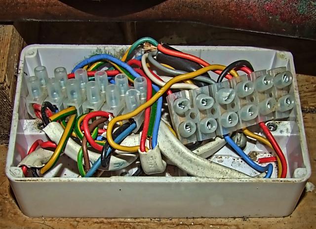
What was 'clear' to him was clear to me, too - the valve wires have unique colours that no other component uses, so no prizes for guessing those. The rest are all red, green and yellow - too many of those to belong to a single source. That, together with the messy look, petrified me.
As you saw in subsequent posts, things started to become clearer (it helps that I have the original manufacturer diagrams), and with the guidance generously provided, it won't be so difficult to resolve.
Cheerz
The orange is boiler and pump,
I found 2 ways to start the heating:
(a) Turn on a hot water tap anywhere in the house and waste a couple of litres of hot water - this kick-starts the circulation pump.
(b) Turn up the cylinder thermostat - to above 70 deg., nearly 80 - does the same. (But water gets too hot with all that follows in terms of comfort, economy and overheating risks).
If you need to find a tradesperson to get your job done, please try our local search below, or if you are doing it yourself you can find suppliers local to you.
Select the supplier or trade you require, enter your location to begin your search.
Are you a trade or supplier? You can create your listing free at DIYnot Local