Changing room thermostat (includes pictures) - Help please

Joined
12 Dec 2006
Messages
130
Reaction score
0
Location
West Midlands
Country
United Kingdom
Hi all,
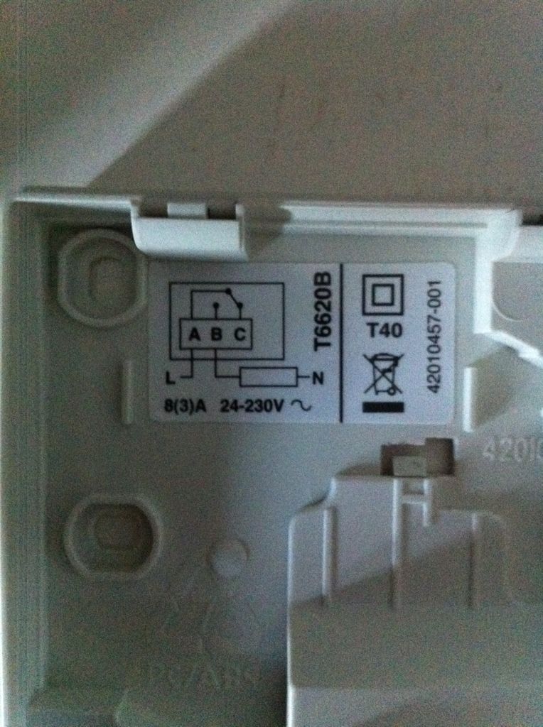
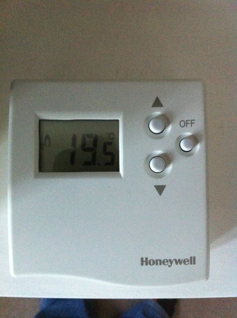
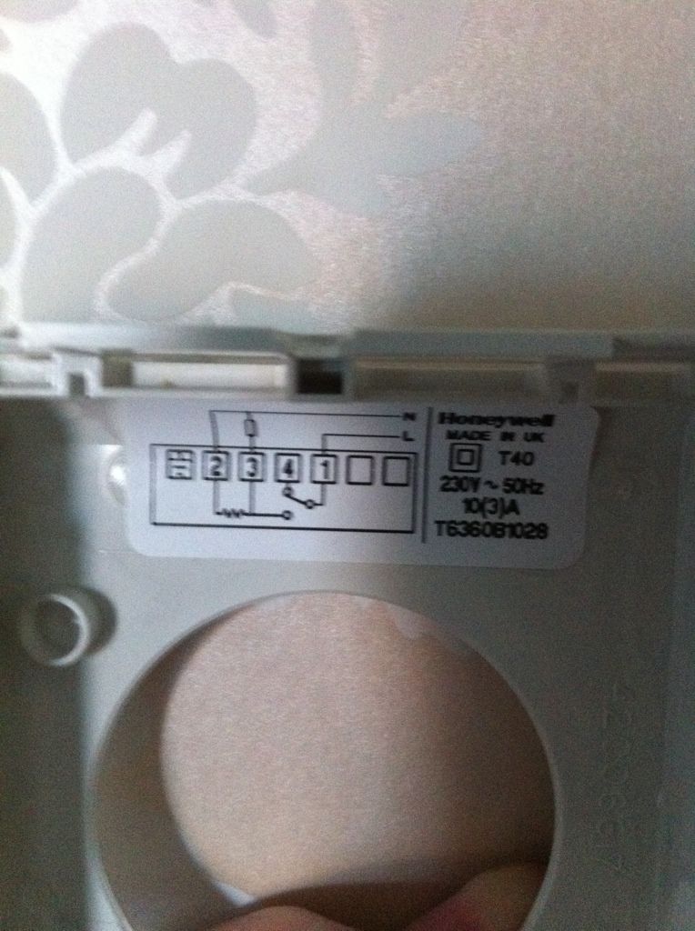
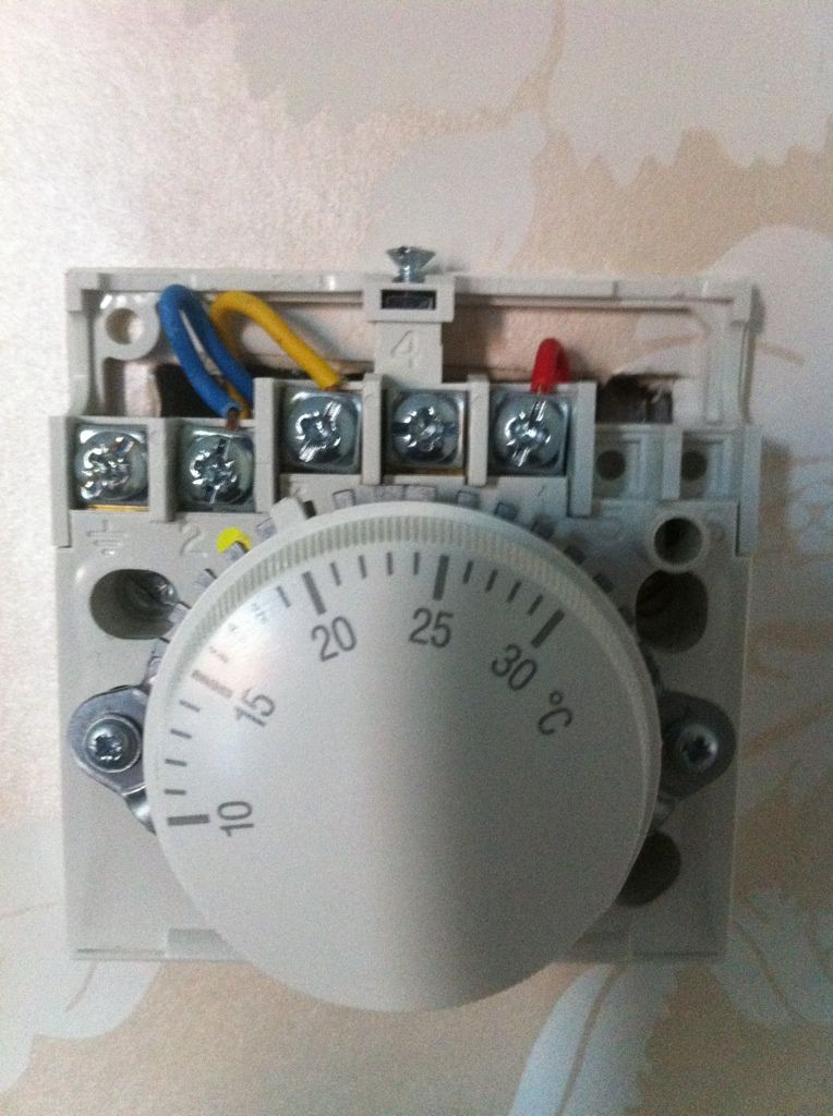
I am looking to change a Honeywell dial thermostat with a digital one, problem is the wiring options are different in both. Thought it would be a simple job!

Can you have a look at the pictures and let me know what you think?

Thanks

2d56933e.jpg

00c15e60.jpg

ee616271.jpg

e60350dd.jpg
 
Sponsored Links
Changing room thermostat
You have a "changing room" in your house? :confused:


Thought it would be a simple job!
It was.

t3038632.jpg


You really should not have needed someone to tell you to take the L that's in 1 as per the top diagram and put it in A as per the bottom one, and to take the one going to the load that's in 3 as per the top diagram and put it in B as per the bottom one.

Doing electrical work without a genuine understanding of what you're doing is a bad idea

Simply following instructions to put the red wire in terminal A and the yellow one in terminal B without actually understanding why is not the basis on which you should be doing this.
 
POP80

Sosme time ago, a number of people on this forum took a lot of time to put a guide with solutions to the most common questions asked. The idea of this is to stop having to answer the same question over and over again.

This guide is called the WIKI and if you had taken the trouble to look it is headlined
Wiki: Please see if the answer to your query is already covered by the Wiki


In the heating controls bit it tells you EXACTLY how to do what you are asking. It is here //www.diynot.com/wiki/electrics:how_to_replace_a_room_stat

You could have found it all on your own without waking BAS up. Now he is gonna be grumpy all the rest of the day.
 
Sponsored Links
I do need to grasp these circuit drawings.
I find them hard to follow.

In the example above first one it looks like live goes to A which will then switch between B and C. C being off and B goes to load.

It was the neutral going to the load. It looks to my mind that you are switching from the live to the the neutral . which is silly.
It is showing the live switching to the switch live which goes on to the load where there is a neutral to complete the circuit. Correct?

thinking out loud...

the original stat needed a neutral. Is this purely to operate the stat. only the live gets sent on, the load will get its neutral from elsewhere. The new stat does not need a neutral as it has a battery for the time clock.

But what did the neutral do on the old stat I thought it was a bimetallic strip that reacted to temp so its a mechanical action, why would this need a neutral.

In the other diagram it looks like the live goes to 1 which switches between 4 and 2 /3
4 does not go any where so is off
3 goes to the load
2 is the neutral
I don't understand the connection between 2 and 3 it looks like the live is going to the neutral via a resistor

If the stat needs a live and neutral to work why are you switching it? Should 1 not be connected to 2 via the resistor.

Thanks to anyone who has the patience to help me out
 
But what did the neutral do on the old stat I thought it was a bimetallic strip that reacted to temp so its a mechanical action, why would this need a neutral.
The bi-metalic strip controlled snap action switch opens at a different temperature to that at which it closes. The neutral is used to supply a small heater ( about 1/2 watt ) that slightly warms the air in the sensor to "trick" the switch into opening and closing at almost the same room temperature.
 
In the example above first one it looks like live goes to A which will then switch between B and C. C being off and B goes to load.
Yes.
It was the neutral going to the load.
No. It's just a switch. The wires do not know what colour they are.
It looks to my mind that you are switching from the live to the the neutral . which is silly.
It would be. If you connect live to another wire then that will become live.
It is showing the live switching to the switch live which goes on to the load where there is a neutral to complete the circuit. Correct?
Yes.
the original stat needed a neutral. Is this purely to operate the stat.
Yes.
only the live gets sent on,
Yes.
the load will get its neutral from elsewhere.
Well, it does not 'get' a neutral. The wire which completes the circuit is called neutral.
The new stat does not need a neutral as it has a battery for the time clock.
Yes. Some just work with the bi-metal strip.
But what did the neutral do on the old stat I thought it was a bimetallic strip that reacted to temp so its a mechanical action, why would this need a neutral.
It must have had internal workings that need power (as Bernard said).
In the other diagram it looks like the live goes to 1 which switches between 4 and 2 /3
Yes. 1 goes to 4 or 2&3.
4 does not go any where so is off
4 would signify that the other devices are off - needed by some Central Heating valves etc.
3 goes to the load
Yes.
2 is the neutral
Yes.
I don't understand the connection between 2 and 3 it looks like the live is going to the neutral via a resistor
It's only 'called' neutral after a load.
The wiggly line represents the internal workings.
If the stat needs a live and neutral to work why are you switching it? Should 1 not be connected to 2 via the resistor
That would be something which is not needed when the heating is switched off.
 

DIYnot Local

Staff member

If you need to find a tradesperson to get your job done, please try our local search below, or if you are doing it yourself you can find suppliers local to you.

Select the supplier or trade you require, enter your location to begin your search.


Are you a trade or supplier? You can create your listing free at DIYnot Local

 
Sponsored Links
Back
Top