Cold Radiator tried almost everything

Thanks, i will be posting them tonight or tomorrow morning as i am at work. The plumber said that he is not comfortable with electronics so he recomended an electrician.
I am very comfortable with electrics so should be easy once i get the diagrams and some tips.
 
Sponsored Links
Here are the pictures as requested. I have labeled as extensively as i could. One thing which i wanted to ask was that i managed to buy another set of x800 and an inhibitor. How long should the x800 be left in the system so as to effectively clean the system without running risk of leaks. I did put the cleaner in last time but some of the rads are still cooler from the bottom. I know taking them off and cleaning them will sort it but i thought the pipe work would need cleaning as well.
Mid position valve
Timer
Pump
 
Thanks for the pics - very helpful.

For some reason I thought that the extra valve put in by your plumber was a motorized valve; but I was mistaken :oops: 
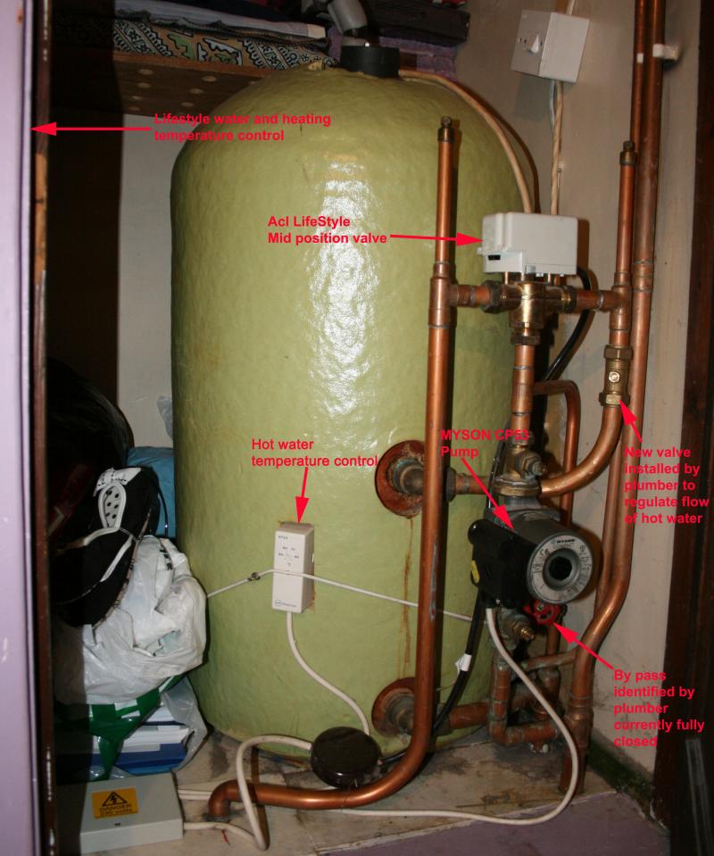
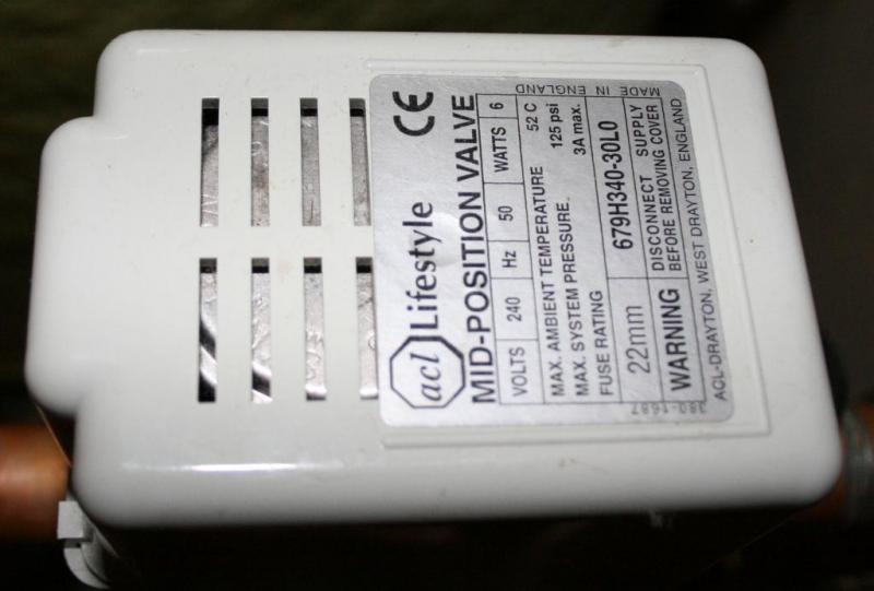
The manual valve he has installed is just to restrict the flow through the cylinder; without it the radiator circuit would be robbed when the ACL mid-position valve is in mid-position, ie, heating and hot water.

The Drayton LP522 can control heating and hot water individually, so there is no need to have both on at the same time - it's just a case of wiring up properly!

Here is the wiring diagram:

8dxytxf.jpg


LP522 Instructions

Post if you need help ;)
 
Thanks for the info.

I was not feeling well over the weekend so couldnt reply or do the wiring. But i did manage to take the control off and check whether it was set to P on the back which it was.

About this diagram which you have sent. I presume this is for the white box which feeds the control. It is on the bottom left of the picture i posted. While looking at it i realized that there is another black round box which feeds it and then connects to the cylinder stat and the valve. Is this right? From the diagram i can see that they do share some connections though. Will investigate further when i open up the circuits.
BTW do you have any info on this mid position valve? Apparently i should be able to move the lever to only work CH or HW. But on trying the lever doesnt move at all.

NOW SOMETHING URGENT
This morning when the central heating came on, after about an hour or so when the boiler fired, it turned off after a few seconds. Usually it fires and stays on for a minute or so. It didnt fire again even after 30 minutes and the house went cold. I checked the control and the red lights were off when they were supposed to be on. I tried pushing the boost buttons but to no avail. I am stumped!! any clues. Any help would be appreciated.
 
Sponsored Links
But i did manage to take the control off and check whether it was set to P on the back which it was.
Good.

About this diagram which you have sent. I presume this is for the white box which feeds the control. It is on the bottom left of the picture i posted.
What, the box lying on the floor!! It should be wall mounted. That's probably the one, it should have one or two terminal connection strips inside.

there is another black round box which feeds it and then connects to the cylinder stat and the valve. Is this right?
This is unusual and is not normally required. If possible, get rid of it and wire everything directly to the wiring centre (white box).

NOW SOMETHING URGENT
I checked the control and the red lights were off when they were supposed to be on. I tried pushing the boost buttons but to no avail.
Check your fuses. The switch on the wall above the cylinder has a fuse in it. Check either with a meter or by putting the fuse into something else, e.g. a table lamp plug. If you just replace the fuse and there is something wrong you will just blow a new fuse.

If the fuse has blown, you need to check the programmer. Disconnect all wires to the programmer except the power in (L, N and E). then turn it on. If the lights come on, check the various options. If no joy, you will have to replace the programmer. There is, of course, a chance that something further down the line, thermostat, motorized valve etc, has caused the problem.
 
The switch on the wall above the cylinder has a fuse in it. Check either with a meter or by putting the fuse into something else, e.g. a table lamp plug. If you just replace the fuse and there is something wrong you will just blow a new fuse.
If you are referring to the one which is on the top right then that is the one for immersion element in the water tank. I dont think that has anything to do with the circuit. Is there another fuse anywhere as the fuse box has all the fuses in on position. I got my Mrs to check it ;)

If the fuse has blown, you need to check the programmer. Disconnect all wires to the programmer except the power in (L, N and E). then turn it on. If the lights come on, check the various options. If no joy, you will have to replace the programmer. There is, of course, a chance that something further down the line, thermostat, motorized valve etc, has caused the problem.
The programmer shows the clock and all the programs. You can even set the new ones. It just doesnt turn on. I think i will have to take a half day today and head back home to sort this. How can i isolate power to the CH circuit? Do i have to power off the whole house?
 
If you are referring to the one which is on the top right then that is the one for immersion element in the water tank. I dont think that has anything to do with the circuit. Is there another fuse anywhere as the fuse box has all the fuses in on position.
OK, My mistake - though it looks as if there are two wires coming out of the bottom of the switch; a cream one , which presumably is the immersion, and a white one. Am I seeing things?

Central heating systems should be protected by either an un-switched fused spur or an un-switched socket. The fuse in the spur or 3-pin plug should only be 3amp. You will need to trace the cables from the white box to find the power connection. If it's not near the cylinder, it might be near the boiler.

The programmer shows the clock and all the programs. You can even set the new ones. It just doesn't turn on.
Looks as if the programmer has a faulty switch or relay. Remove the programmer and note the colours of the wires connected to terminals 1,2,3 and 4. Replace the programmer. Find the other end of each wire (probably in the white or black box) and temporarily disconnect any other cable connected to the same terminal - note what they are so you can reconnect!. Turn the programmer on and check each terminal for 240V with a meter. The wires connected to programmer ON terminals should read 240v when CH/HW is turned ON; the OFF terminals should read 240v when CH/HW is turned off.

If any of them do not read 240v, the programmer is broken.
 
OK, My mistake - though it looks as if there are two wires coming out of the bottom of the switch; a cream one , which presumably is the immersion, and a white one. Am I seeing things?
No you are not. It does run all the way upto the loft and all the way down but havent got a clue.

Anyway that problem is sorted and i had a laugh. Found the culprit and it is
must have switched off when chucking the hoover in there before leaving for work in the morning.

About the wiring it is doing my head in. The board is 12 position and many connections are different. Here is the two pictures. By the way the black one only acts like an extension for the mid pos valve. I am unable to find which feed is from the boiler and which one is from hallway stat.
EDIT
Spent about 3 hours looking through the wiring. Terribly confusing specially when looking at your diagram as it is set out completely different. It also conflicts with the one in the LP522 manual which you sent the link for. Anyway by looking at the one in the LP522 manual, even though my wiring is not set out exactly on the right slots but the corresponding connections are fine. I can say that for Valve and the Programmer. I opened the valve as well to check if the micro switch makes contact which it does. I have been playing up with the arm of the valve and here are my findings.
1. When the arm is moved towards right
a. If heating advance is pressed, nothing happens
b. When hot water advance is pressed while heating advance is on nothing happens.
c. When hot water advance is pressed while heating advance is off the arm moves to mid position when engaged and to left when not engaged.

Now i was just wondering what could be preventing the heating to come on without hot water. Any connections i should check?[/b]
 
The valve moves over two stages. stage 1. power from programmer feeds room stat, then power from room stat feeds the 'white' wire of valve. This drives motor to mid point when micro switch No 1 is triggered.
As HW is not on, there is also a power source from the programmers HW OFF terminal which is fed to the 'grey' wire of valve. So the M/S No 1 has 2 inputs (white and grey) but only 1 output. So at mid point it switches from the white to the grey. stage 2. The grey drives it to the CH only position and it is held there for as long as the motor remains energised.
During stage 2 micro switch No 2 is triggered. This M/S No 2 is also fed from the 'white' wire, but its output is the 'orange' wire of the valve.
So if valve moves to mid point, then room stat is ok, which leaves a query regarding the 'grey'. Does the wire from programmer exist?

Now if the HW was on, the 'grey' would not be live anyhow! cause HW/ON/OFF is like two way switch (only one can be live).
Now the cylinder stat is also like a two way switch, power from HW ON feeds the HW stat and fires the boiler, but when temperture is satisfied the power is diverted out of the 3rd terminal of stat and it joins the 'grey'
See diagram.

Either the valve is moving across to CH only and it does not light boiler due to faulty micro switch No 2, or the valve is not moving across to CH only position, due to incorrect wiring or faults in actuator head (eg motor or M/S No 1)
Hope it may help a little!
 
Now if the HW was on, the 'grey' would not be live anyhow! cause HW/ON/OFF is like two way switch (only one can be live).
Now the cylinder stat is also like a two way switch, power from HW ON feeds the HW stat and fires the boiler, but when temperture is satisfied the power is diverted out of the 3rd terminal of stat and it joins the 'grey'
See diagram.
Thanks Mandate, were you going to attach a diagram or otherwise which diagram are you referring to? As far as micro switches are concerned, when i opened the valve i did note that there seemed to be two but only one at the bottom use to make contact the top one didnt. Is that wrong?

I was really confused at the point where i had to check the wiring from the room stat as it doesnt state clearly which wires are which. I could check the programmer wires by taking the head off but for the room stat its a matrix of symbols which i dont know about.

I am not a professional so am not familiar with the terms but i am coming to grips with them. What do you mean by M/S 1. I presume you mean the circuit board where all the connections are made but that only has the two live wires.
 
I am quite certain Mandate is correct in his explanation, however I found this when I had to modify my system to operate from a cooker/boiler. Try this link for an excellent description of the Mid point valve.
www.diyfaq.org.uk/plumbing/controls then go to midpoint valve.
 
I am quite certain Mandate is correct in his explanation, however I found this when I had to modify my system to operate from a cooker/boiler. Try this link for an excellent description of the Mid point valve.
www.diyfaq.org.uk/plumbing/controls then go to midpoint valve.

Cant get onto the website from the link. It says 403 forbidden. Could you please resend the link.
EDIT:
Never mind here is the correct link http://www.diyfaq.org.uk/plumbing/controls/midpositionvalve.htm
 
I was referring to the diagram posted by D hailsham.
As stated it's a two stage function. The live 'white' switched on by room stat caters for the first leg. The second leg is catered for by the 'grey' which is powered from either the 'cylinder stat' (if HW satisfied) or the wire from HW OFF terminal of programmer (if HW not on).
Its during the second leg micro switch No 2 is triggered to allow power out of valves 'orange' wire to light boiler( in lieu of cylinder stat).
Microswitch No 1 is fed from 'white' and 'grey' wires and is triggered at mid point to change from one supply to the other.
If for example the 'grey' has reduced voltage or does not exist then valve will never move beyond mid point, so it's important to verify the wiring on this part is correct.
If you select CH only and the boiler lights, it suggests its functioning ok and you can feel at the pipes leaving the 3 port valve.(HW coldish CH hot).
Now if boiler does not light its because either micro switch faulty or micro switch not triggered by valve not having moved to correct position.
 
Found the culprit ...must have switched off when chucking the hoover in there before leaving for work in the morning.
By culprit, do you mean the main switch for the heating system?

About the wiring it is doing my head in.
Not surprised - it looks a mess.
The board is 12 position and many connections are different.
Have you worked out that No 1 is on the right as you look at the picture? I can't work out what the odd wire into T11 is doing - there's nothing connected to it.
By the way the black one only acts like an extension for the mid pos valve.
That's what I deduced from the pics!
I am unable to find which feed is from the boiler and which one is from hallway stat.
That needs to be done. I also can't see the mains input cable going to terminals 1-3, unless mains goes first to the boiler, via the switch you found, and a cable comes from boiler to T1-T3.
Terribly confusing specially when looking at your diagram as it is set out completely different. It also conflicts with the one in the LP522 manual which you sent the link for.
It's a pity everybody does not stick to the same wiring, Honeywell's diagram has been around for years. The only difference between the Honeywell and Drayton diagrams is that terminals 7 and 8 are swapped over; i.e Honeywell 7=Drayton 8 and vice versa.
 

DIYnot Local

Staff member

If you need to find a tradesperson to get your job done, please try our local search below, or if you are doing it yourself you can find suppliers local to you.

Select the supplier or trade you require, enter your location to begin your search.


Are you a trade or supplier? You can create your listing free at DIYnot Local

 
Sponsored Links
Back
Top