Controller connections, changing from Danfoss to Honeywell

Joined
23 Jan 2008
Messages
52
Reaction score
0
Location
Glasgow
Country
United Kingdom
Hi everyone

Having had a new combi fitted, we are changing our controller from a Danfoss TP5 to a Honeywell CM907.

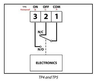
My question is how the connections correspond. The wiring diagram shows basically the same system, but I wanted to be sure before going for it.

The Honeywell has three terminals marked A, B and C

The Danfoss has: 1 (COM) 2 (N/C) and 3 (N/O)

Any help is gratefully received
 
Sponsored Links
Having had a new combi fitted,
Which boiler - make and model?

Some boilers need "volt-free" switching at the programmer; others take their 230v supply from the programmer.

How you connect up the CM907 depends on the boiler.
 
A is your new Common, Com or 1
B is your new Normally Open, N/O or 3
C is your new Normally Closed, N/C or 2
 
Sorry - should have said

Worcester Bosch 37CDi

We went for the Honeywell as the WB controllers are too difficult to learn how to use.

Thanks
 
Sponsored Links
Thanks guys - I could be wrong but there seems to be a difference of opinion, basically on polarity of live and neutral.

BGEngineer suggests that the Honeywell terminal A is COM (neutral I assume) while D_Hailsham suggests this same terminal is Ls (which I assume to be constant live, looking at the boiler manual).

Am I right in thinking:

Ls - constant live
Lr - switched live (used to switch boiler at timing/programmer events)
Ns - Common/neutral

Is my boiler a no volt system (i.e not switching 230V to boiler)

Looking at the switching diagrams for both controllers it seems to be that

Danfoss Honeywell Boiler connection

1 COM A Ns
2 N/C C Ls (constant live?)
3 N/O B Lr (switched live?)

This is what BGEngineer suggests and looks to me to be correct based on the diagrams of the switch from each controller. From my understanding both of you guys suggest connecting the switched live (assuming this is what Lr means) to terminal B.

The only difference therefore is the polarity of the constant live and neutral at terminals A and C. Is my understanding correct and if so, is the polarity crucial?
 
BGEngineer suggests that the Honeywell terminal A is COM (neutral I assume).
Terminals A and COM both perform the same job, they are NOT Neutrals. The Danfoss and Honeywell programmers are battery powered and do not need a neutral connection.

You said:
Am I right in thinking:
Ls - constant live
Lr - switched live (used to switch boiler at timing/programmer events)
Ns - Common/neutral
Yes, that is correct for the boiler terminals.

You said:
Is my boiler a no volt system (i.e not switching 230V to boiler)
Yes, the boiler is fed directly from the mains to the L, N, and E terminals of ST10. The boiler is turned on/off by having a switch (e.g. programmer or thermostat) which links the Ls and Lr terminals. This has to be a volt-free switch.

You said:
Looking at the switching diagrams for both controllers it seems to be that

Danfoss Honeywell Boiler connection

1 COM A Ns
2 N/C C Ls (constant live?)
3 N/O B Lr (switched live?)

NO that is incorrect. You need to get a better informed BG engineer!

This diagram shows what the terminals do. As you can see, A/COM is the feed to the switch, which can either connect to B/ON or C/OFF. You therefore need to connect the Ls terminal to A/COM and the Lr terminal to B/ON. The B/OFF terminals are not used.

 
Thankyou once again - I'm very grateful.

My (hopefully) last question then:

Would you be able to confirm the connections in terms of the Honeywell A, B and C terminals based on how the Danfoss was wired.

I completely understand everything you've said, but can't get under the floor to check the continuity of the cables used to connect the boiler to the controller. There was an extension to the original cables when the boiler was moved and the floor is now tiled above the junction box that was used to extend the run. The cores at the boiler bear no relation to the colour of cores used at the controller and as a result I don't know which is connected to Ls and which is Lr.

Basicallly, if you could tell me where Ls and Lr are connected at a Danfoss TP5 then I can take it from there.

Thanks again
 
if you could tell me where Ls and Lr are connected at a Danfoss TP5 then I can take it from there.
Ls should be connected to the COM terminal and Lr to the ON terminal. So the wire connected to Danfoss COM should be connected to Honeywell A; and the wire connected to Danfoss ON should be connected to Honeywell B.

If you want to be doubly sure, use a meter/mains tester to check which wire is live when the thermostat is turned down. This wire should go to A and the other to B.
 
Hang on there a minute nothing I have said is incorrect:

The diagram you have posted is for his old room stat the Danfoss, if you follow this link you will find the wiring diagram for his new one the Honeywell:
http://europe.hbc.honeywell.com/products/pdf/en0h8547uk07r0906.pdf

A is your new Common, Com or 1
B is your new Normally Open, N/O or 3
C is your new Normally Closed, N/C or 2

Live Supply (LS) to A, this is your common.
Live Return (LR) to B, this is your switch live or normally open.

Sludd think of a room stat like this. Common is always powered and then channels this power between the Normally Closed terminal (when stat is turned down) and the Normally Open terminal (when the stat is turned up). If you compare the Honeywell wiring diagram to the Danfoss one D_Hailsham posted you will see what I posted was correct.

Its ok D_Hailsham i'm not expecting any flowers or anything.
 
Thanks BGE - I'd already checked back to your original reply and realised you were on the money. My confusion lay in my not knowing how the existing Danfoss connections related to the Ls and Lr at the boiler, due to the cable run being extended. Your first post meant this didn't matter - it was trying to work out the relationship of danfoss controller to boiler terminal that got me confused

If there is a third core connected at the Danfoss when I remove it, should I connect it to the other terminal in the Honeywell or cut it back an leave unconnected.

Also, when it comes time to make the changeover, should i power down the boiler or is there a standard procedure to follow
 
Yeah its not required, just strip it back and isolate it. When you do this, your boiler should have a 3amp fuse spur located near it just switch this off and confirm isolation.
 
Sorry to bother you again chaps

I was about to do the job of changing controllers this morning and decided to do a bit of checking first.

It seems that the controller does indeed switch between the COM and Lr (normally open) but it seems to switch 240V rather than the low voltage I had expected.

Regardless of this, the existing Danfoss controller works fine but just wanted to check this is OK and what it should be before I change to the Honeywell - don't want to blow the new controller
 
All done!

Checked the Honeywell and it was rated 12-240V so figured it was OK. Everything seems to be working fine and also installed a new fused spur for the boiler (original hadn't been re-instated) and proper junction boxes for the extended wiring, both mains and controller.

Thankyou for all your help
 

DIYnot Local

Staff member

If you need to find a tradesperson to get your job done, please try our local search below, or if you are doing it yourself you can find suppliers local to you.

Select the supplier or trade you require, enter your location to begin your search.


Are you a trade or supplier? You can create your listing free at DIYnot Local

 
Sponsored Links
Back
Top