Correct weight for 130mm celotex in kN/m2 at 0.25?

Reply from SE...

-----
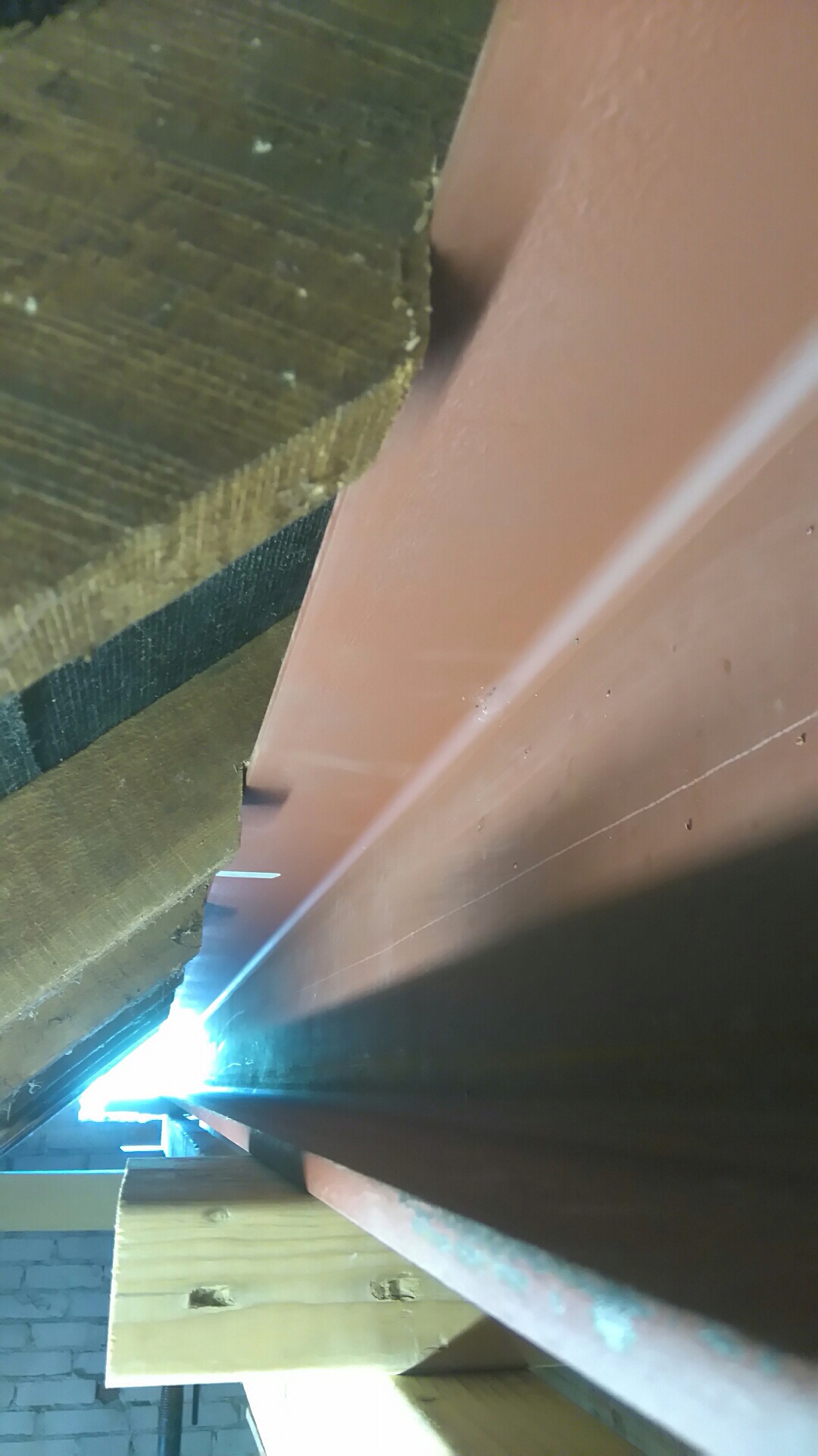
The steel beam needs to be a 305x 165 x 40UB s275. Or a 203 x 203 x 46 UC s275.
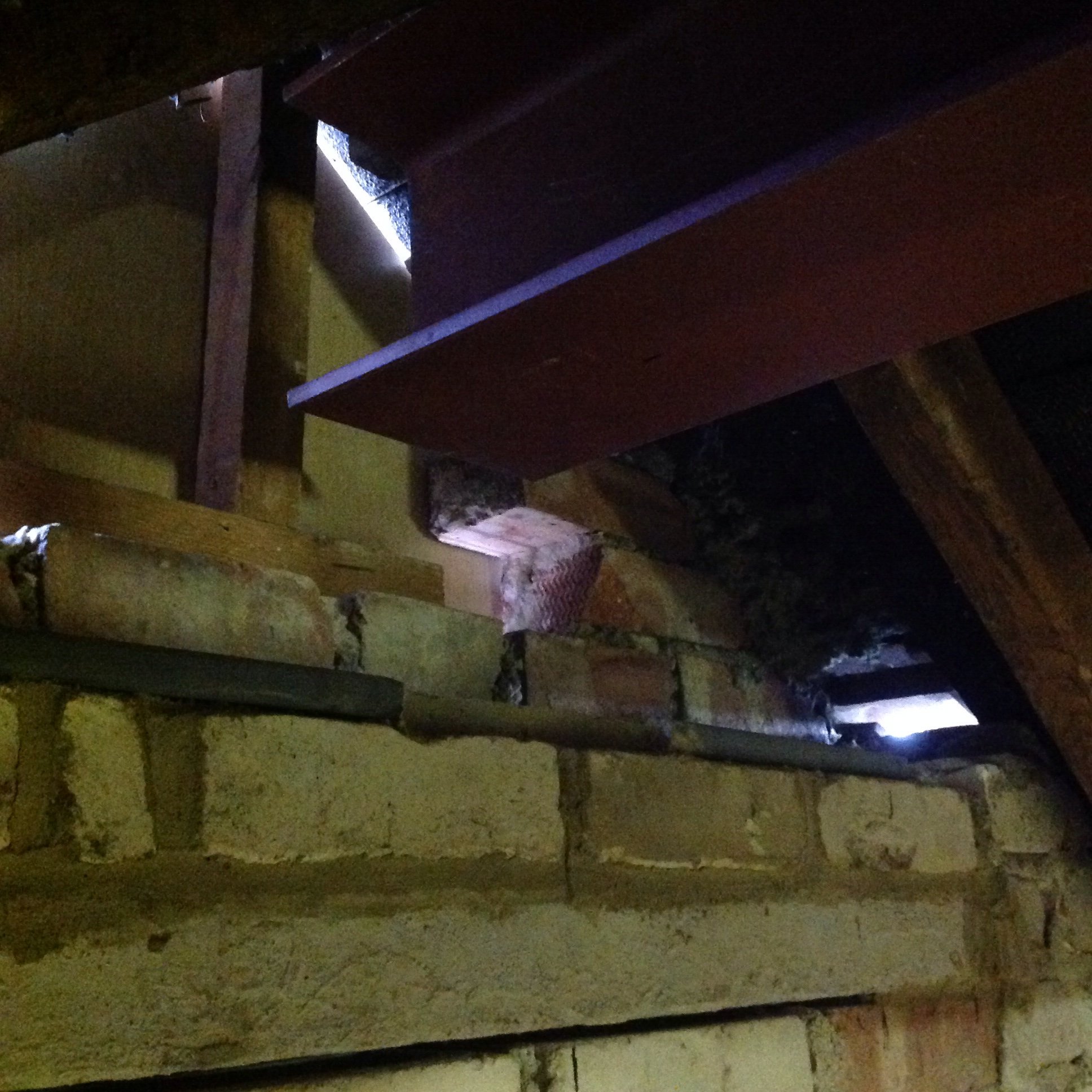
As the beam has no real end lateral restrain, i.e. It can rotate as there is insufficient brick work to stop the beam from rotating, British Standards request me to increase the beam design by 1.2L. As the beam is laterally un-restrained.

Bearing plates are required if the block work has a compressive strength less than 7.00N/mm.sq. this is your builders call. Personally, I prefer seeing them in.
-----

I have white engineering bricks as used in 1950...
 
Sponsored Links
You normally bolt a 2" thick piece of timber into the web of the steel beam each side, and then have the top of the steel beam level with - or just a touch below - the top of the existing timber ridge board. You then nail through the ridge board (from the tiled side) into the timber in the web.

On the flat-roof side, you run the roof joists directly into the timber insert and secure with joist hangers and/or skew nailing. Once the roof boarding is on, the roof acts as a rigid plate and this and the incoming rafters from the front will hold the beam along its length. This means you can take the effective length as the actual length (6m), which is more realistic than using a figure of (effective length) x 1.2. In this instance, the type of restraint at the support does not matter in practice.

The dead loads quoted are a bit on the high side (eg insulation); and Welsh slate is usually thin and not 0.5 kn/m2. A slightly more realistic load on the 6m length gives a more practical beam and a 203 x 133 x 30 would be be fine. If you wanted to go really overboard you could consider one of the 254 x 146 beams (but not necessary and might reduce your headroom) but a 305 x 165 ??!! or a 203 x 203,
OMG!!!!!
 
Thanks,
Due to the brevity of the drawings I am having to interpret where beam A will actually sit. My initial thought was this was directly below the ridge beam. I have no drawings supplied to show this location ,such as a cross section, and SE said any competent loft converter will know where it goes... V unhelpful.

I ask this as the 20mm 400 100 steel plate is listed as sitting at both ends of the ridge beam but that doesn't make sense when one end is sitting on the steel post (and bolted to it) , the other on beam A (I think)

It's not unreasonable for SE to draw where these beams connect or am I expecting too much...?
 
Is it possible that he hasn't realised that one end is bolted to a steel post, and as being bolted to the steel post would stop any rotation, has he overspeced the size of the beam.

And going back to your opening post, what is the thickness of the insulation, as that could explain the difference to the plasterboard.
 
Sponsored Links
Yes sorry original question has morfed into a beam query. Insulation 130mm
I'm sure SE knows it is bolted to a post but does not want to back down over size...
 
I am looking at the calculations given to me for a 6m ridge beam that has come out a 203x203, 46kg and it seems huge to me for a ridge beam.

I've also just been specified a 203x203x46 for a 6.4M span, supported at both ends by gable walls and only carrying 45 degree rafters and concrete tiles at 47KG/M2. I'd resigned myself to a crane but perhaps I also need to look a bit harder at it? I'd assumed that as a beam gets longer it's section becomes disproportionately large just to support its own weight?
 
I've also just been specified a 203x203x46 for a 6.4M span, supported at both ends by gable walls and only carrying 45 degree rafters and concrete tiles at 47KG/M2. I'd resigned myself to a crane but perhaps I also need to look a bit harder at it? I'd assumed that as a beam gets longer it's section becomes disproportionately large just to support its own weight?

It's often the deflection of the beam which is critical, particularly on longer spans; deflection of a beam of any given section is proportional to the cube of the span.

Edit

Eek, what was I thinking of??!! Double the span and you increase the deflection by a factor of 8. (I must ask the College for my tuition fee back)

 
Last edited:
It's often the deflection of the beam which is critical, particularly on longer spans; deflection of a beam of any given section is proportional to the cube of the span.
Indeed, The only extra factor which scales badly is the self weight of the beam, as it gets longer and deeper it increases by a factor of n2. Hence why you can only span so far with c16 timber.

Also the deflection is inversely proportional to the cube of the depth, which is why the depth and span are almost directly related, although I could never quite get my head round why the deflection is related to the cube of the depth from an intuition point of view.

In proportion because of twice the material (easy)
Squared because the extra material is twice as far from the neutral axis, and then
Cubed because ?

Any ideas?

Edited to add the missing word "cube"and clarify a little
 
Last edited:
Also the deflection is inversely proportional to the depth,

Any ideas?

Not quite - for a simple rectangular section, deflection is inversely proportional to the cube of the depth. For more complex shapes like I-beams
(which are really three rectangles), deflection is inversely proportional to the Moment of Inertia of the section (don't ask!!!).
 
Not quite - for a simple rectangular section, deflection is inversely proportional to the cube of the depth. For more complex shapes like I-beams
(which are really three rectangles), deflection is inversely proportional to the Moment of Inertia of the section (don't ask!!!).
Sorry, brain and fingers not on the same page, I did mean to write the cube! I'll edit.:oops:
So in that case my question is why is the moment of inertia of simple timber sections related to the depth cubed as opposed to the depth squared?
 
OK now think I worked it out intuitively...
Proportional from the quantity of material
Squared from the extra distance of the "lever" (average position of the material) from the "fulcrum" (neutral axis)
Cubed from the extra distance along the beam that the additional material can have an influence (think herring bone struts)

Make sense or have I done some double counting?
 
Hi,
Perhaps I should start another post but as it is to do with this beam ( now installed partly) I'll leave it here for now.
Question. Should the new ridge beam sit directly on top of the 127x76 13? It seems such a small beam with only a 4mm centre yet I'm about to sit pretty much the whole roof and the new beam on it. Also what should the cement to sand ratio be for bedding the bricks below it in?
Thanks
 
Here is the beam over the gable end wall without the smaller steel installed yet.
should the ridge beam sit directly on this small beam?
Thanks
 

DIYnot Local

Staff member

If you need to find a tradesperson to get your job done, please try our local search below, or if you are doing it yourself you can find suppliers local to you.

Select the supplier or trade you require, enter your location to begin your search.


Are you a trade or supplier? You can create your listing free at DIYnot Local

 
Sponsored Links
Back
Top