Door Bell issues

Joined
16 Aug 2012
Messages
642
Reaction score
20
Location
London
Country
United Kingdom
Afternoon all,

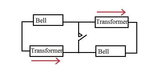
I have 1 bell button, two bells and two transformers, which up until 2 weeks ago were working fine - you pressed the button and both bells worked.

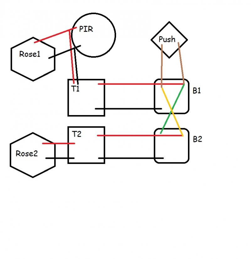
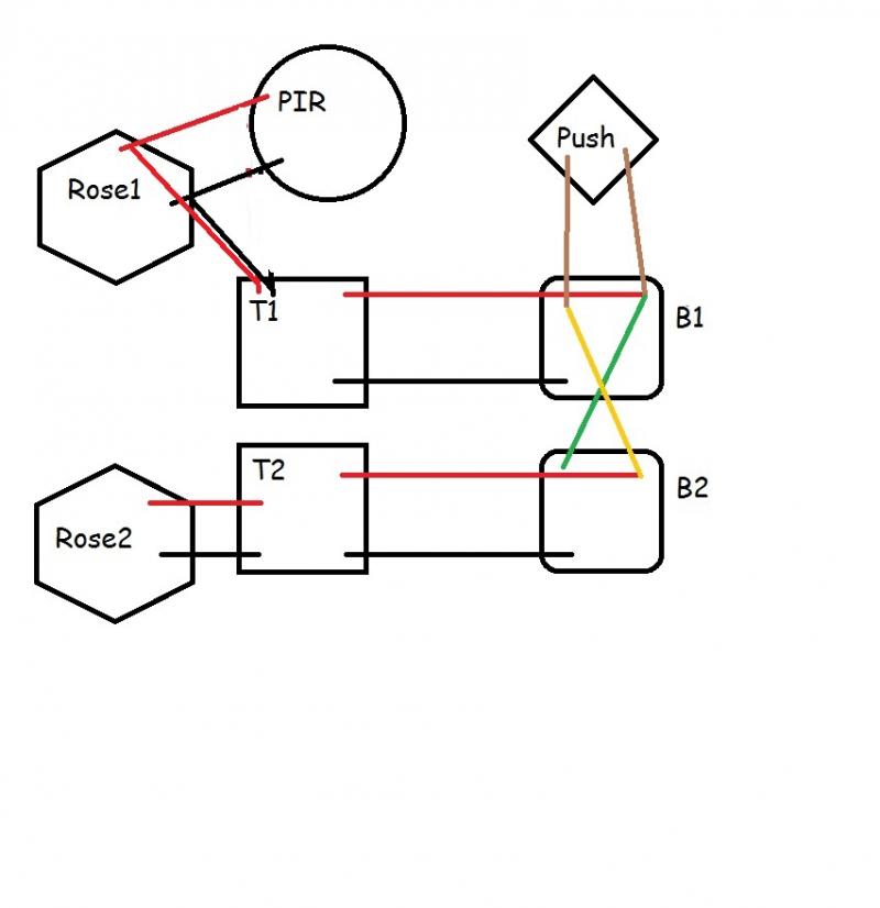
One transformer was being powered from the live on one light fitting, and the other was from the perm live into a PIR.

I disconnected it from the PIR end as it was an unsafe connection (just a choc block with insulation tape round it) and connected it into a junction box at the light fitting side which was powering the PIR.

Now the problem i have is, when ever i connect the front transformer, it the front bell stays energized. regardless of if the bell button is pressed. If i disconnect the bell wire and carry out a circuit test, there is no connectivity at the bell connection point of the button. so its not a stuck button.

If i disconnect the front transformer from the mains, the rear one carry's on working as normal. (and how it currently is)


The setup was functioning without problems for a couple of years, all that's changed is the power for the front transformer is taken from a junction box side of a live cable, instead of the PIR side of the live cable...


Any ideas on what could be going wrong or what else i can test?
 
Sponsored Links
To be honest, I had trouble understanding this.

My interpretation is that you have two transformers, each of which operate a bell, but there is only one bell push between them.

How exactly is one bell push wired to two transformers? Is it a dual pole switch, or is there an isolating relay somewhere?

Here are a couple of suggestions based on the symptoms you describe

Scenario 1. Is that the PIR is not a PIR but a relay, the contacts of which were wired to energise the transformer and sound the bell. Now you have wired the transformer directly to a permanent supply it operates continually.

Scenario 2. A little more unlikely but possible. Assuming you do have a PIR, I can offer the following possible explanation. The transformer that is now operating continually may have been connected to the switched side of the PIR, so that when the PIR detected someone, (reaching for the bell push perhaps) it energised the transformer and caused the bell to ring. Now you have connected it to a permanent supply it rings permanently.

In both cases, the other bell is connected to the bell push and is still working OK.

All I can suggest, is to put the wiring back as it was, and see what happens then.

To give a more definitive answer, either photographs of all of the components and their wiring connections, or a sketch of the wiring showing both the mains supplies, and both bell circuits would be required.
 
Thanks for the reply stem,

I'll double check the connections and make a drawing of both by the weekend.

The setup is correct, 1 door bell button, makes two bells ring (one at the front of the house and the second at the back of the house). Both bells are individually powered by their own transformer.

From what i can see on the wiring, the two bells are piggy backed - will hopefully come clearer with the diagram.
 
Sponsored Links
Finally got a chance to check these,

Drawn up the before and after for the setup

T1 is transformer 1 feeding bell 1.
T2 is transformer 2 feeding bell 2.

The bells have the following connections:

top left is "OF"
top right is "1"
bottom left is "T3"

The solenoid is connected between OF and T3

Both bells are the same but the transformers are different to each other.

Looking at the setup, top right (1) is used to provide 6V, and bottom left (T3) is used as 0v.

Bell button is connected between OF and 1.

There is a pair of wires going between - Green and Yellow but they seem to be crossed... where On bell 1, green is from "1", but connecting to "OF" on bell 2 and yellow is the reverse.

The before:

The after:


Only things I changed as mentioned is where T1 was getting its power from.

Now something sprung to mind as I drew this up, either I have now connected t1 up reversed (as in live and neutral have been swapped - though I checked when I connected it up), or they were swapped before and are now correct, with the crossing green and yellow now causing the 0v from t2 and the 6v from t1 to make Bell 1 stay open?

Going to disconnect B2 all together when I get a chance and see if b1 then works normally, as well as check for reversed polarity…

but meanwhile any other suggestions to check would be appreciated - its a bit of a pig (its behind a ceiling panel in a small porch with just about enough space to get a ladder in) to get to the wires for T1, and the location itself, plus i have to close it all up when I'm done checking so would rather check as much as possible each time.

Re the comment about two transformers – that’s what I’ve inherited so to speak with the house… when I get the house rewired I’ll change it to a single or most likely just go wireless!
 
Solved.... Wife wouldnt let me sit till i checked re crossed wires... Turns out that the wires ive moved are correct, onlt thing was the green/yellow wires which go between the two bells. Swapped them over on one bell and all now works. I can only assume somewhere inthe past the first transformer got its feed reversed. By moving the wires ive corrected it and then had to adress the cross over between the bells
 
The two transformers, the two bells and the push are connected as below


( primaries of transformers omittted for clarity )

The two transformers are in anti-phase and thus if they are the same voltage they cancel each other out and there is no voltage to drive the bells. Losing the mains to one transformer means the other transformer's output is shared between the two bells and one or both will ring without the button being pressed.

Press the bell push and each transformer is connected to a bell.

I think that was exactly what was happening... and i can only assume that it got that way because the primary on transformer 1 was switched in the past, and now been corrected ( i checked polarity with a multimeter) red to live and black to neutral showed as +240, black to live and red to neutral showed -240.

Who only knows what other funny wiring i will find in this house...
 

DIYnot Local

Staff member

If you need to find a tradesperson to get your job done, please try our local search below, or if you are doing it yourself you can find suppliers local to you.

Select the supplier or trade you require, enter your location to begin your search.


Are you a trade or supplier? You can create your listing free at DIYnot Local

 
Sponsored Links
Back
Top