Electronics question

Joined
20 Apr 2017
Messages
73
Reaction score
1
Country
United Kingdom
I know this forum is full of electricians, but I'm hoping one of you guys is also an expert in electronics and can help me with a project.. if so, keep reading!

I am trying to run a 56V Ego leaf blower on a timer, using a remote momentary switch.

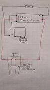
The timer relay I am using is a Tele E1ZM10

The control circuit is 12VDC.
Terminals 15 and 18 are used to replace the trigger microswitch on the blower.

Everything works fine - when the momentary push button is pressed, the 12V circuit completes momentarily and the relay contacts close for a set number of seconds. So the blower turns on for this number of seconds. Great. Except every now and then, (maybe once in 50 or so pushes) the blower stays on. The relay LED indicator shows that it has stopped counting and the relay contacts have opened, except the blower is still on. I've since realised that with the blower connected, there is 24V between 15 and 18, which is coming from the blower itself. So I'm assuming (as a novice) that the motor controller in the blower is sometimes holding the relay closed. So I wanted to fit a diode to stop this. I've no idea on the current but I was guessing a 60V 5A diode would do the trick. But where would it go? Logically I was thinking it would go between 18 and the return wire to the other side of the microswitch. But I have seen that people put diodes across the coil instead to stop back feed. If anyone is still reading and knows what I'm on about, then stand by and I'll try and post a picture.

A short term fix is to just press the push button again, and the relay returns to normal operation, but I need this to be reliable. I could always use an electromagnetic solenoid to physically push the blower microswitch on, but I'm worried about how much current this would draw as I'm on limited 12V battery power. Any thoughts gratefully received.
 

Attachments

  • 17030244896934182626925503926083.jpg
    17030244896934182626925503926083.jpg
    117.6 KB · Views: 41
Last edited:
Sponsored Links
I have no idea of the polarity of the blower control voltage so I've made a random guess, in green I show positive +ve to Cathode (stripe on diode) and negative -ve to Anode... Ask more if not sure.
The polarity of the relay contact is irrelevant.

Without knowing what the Blower switch is operating a 60V diode may not be suitable, if it's switching say a 100W motor directly I'd be looking at more like 500V, random item: https://www.ebay.co.uk/itm/133710256028?chn=ps&_ul=GB&_trkparms=ispr=1&amdata=enc:1_8of7_HRSfmCkblePZSFNA33&norover=1&mkevt=1&mkrid=710-134428-41853-0&mkcid=2&mkscid=101&itemid=133710256028&targetid=1647205088800&device=c&mktype=pla&googleloc=1006907&poi=&campaignid=17206177401&mkgroupid=136851690655&rlsatarget=pla-1647205088800&abcId=9300866&merchantid=101449491&gclid=Cj0KCQiAm4WsBhCiARIsAEJIEzUoFMIGzT_pXhR83jy_iDOpd5b3RttVCuIDPcUdW9yvwf2bXtfqLzEaAgXeEALw_wcB

The relay contact is unable to influence the operation of the electronic timer.

I assume you are using Ws setting.

I assume the switch circled red is just an on/off and not part of the timing.


1703032032144.png
 
Links in this post may contain affiliate links for which DIYnot may be compensated.
The contacts of the timer relay should be entirely separate from the control side, so I'd be supprised if the leaf blower was interferring per-see with the operation, more likely in my mind, considering this is only occasional is that the leaf blower is welding the contacts of the relay shut momentarally, in which case the free wheeling diode as drawn by sunray would help, you have got to get the polarity right though. However it might be better to fit a more heavy duty 12V relay to do the actual switching, rather than have the small relay in the timer module do this

Edit: I'd probably still fit diodes though, both across the contact thats switching the leaf blower switch, as well as across the coil of the new bigger relay (although the back emf if a relay coil should be magnatudes smaller than that of a leaf blower)

@Mecca , whats the application of this is I may ask?
 
Last edited:
The contacts of the timer relay should be entirely separate from the control side
In theory that is true but when the relay in the timer is switching OFF an inductive load a back EMF pulse will be created across the relay contacts, The voltage of this back EMF pulse can be be many times the operating voltage of the inductive load.

Capacitive coupling inside the timer could couple the energy of this back EMF pulse onto the timer's control circuit and cause a change mode from Timed to Continuous.

Sunray's suggestion to fit a back EMF diode is a good idea as it will reduce the size of the back EMF pulse
 
Sponsored Links
The contacts of the timer relay should be entirely separate from the control side, so I'd be supprised if the leaf blower was interferring per-see with the operation, more likely in my mind, considering this is only occasional is that the leaf blower is welding the contacts of the relay shut momentarally, in which case the free wheeling diode as drawn by sunray would help, you have got to get the polarity right though. However it might be better to fit a more heavy duty 12V relay to do the actual switching, rather than have the small relay in the timer module do this
I was rather tempted to make the same suggestion but from memory I think the timer contacts are about 10A and I doubt the blower is more than 100W (~4A @ 24V) which allows a 100% inrush margin.
 
Do you switch the 12 volt supply switch ON and then press the button very soon after the 12 volts is applied to the timer, ?

The mode switch is read when the 12 volts is applied to the timer as part of the power up sequence. If the time between applying the 12 volt and the button being pressed is very short then the timer may not have had time to read the mode switch.
 
I have no idea of the polarity of the blower control voltage so I've made a random guess, in green I show positive +ve to Cathode (stripe on diode) and negative -ve to Anode... Ask more if not sure.
The polarity of the relay contact is irrelevant.

Without knowing what the Blower switch is operating a 60V diode may not be suitable, if it's switching say a 100W motor directly I'd be looking at more like 500V, random item: https://www.ebay.co.uk/itm/133710256028?chn=ps&_ul=GB&_trkparms=ispr=1&amdata=enc:1_8of7_HRSfmCkblePZSFNA33&norover=1&mkevt=1&mkrid=710-134428-41853-0&mkcid=2&mkscid=101&itemid=133710256028&targetid=1647205088800&device=c&mktype=pla&googleloc=1006907&poi=&campaignid=17206177401&mkgroupid=136851690655&rlsatarget=pla-1647205088800&abcId=9300866&merchantid=101449491&gclid=Cj0KCQiAm4WsBhCiARIsAEJIEzUoFMIGzT_pXhR83jy_iDOpd5b3RttVCuIDPcUdW9yvwf2bXtfqLzEaAgXeEALw_wcB

The relay contact is unable to influence the operation of the electronic timer.

I assume you are using Ws setting.

I assume the switch circled red is just an on/off and not part of the timing. I can work out the polarity if the microswitch voltage with a multimeter so that shouldn't be a problem

Thanks for this diagram. Yes, the switch circled red is just used for initial power up, not part of the timing. I've set it to Ws to avoid repetitive button pushes resetting the count.
 
Links in this post may contain affiliate links for which DIYnot may be compensated.
The contacts of the timer relay should be entirely separate from the control side, so I'd be supprised if the leaf blower was interferring per-see with the operation, more likely in my mind, considering this is only occasional is that the leaf blower is welding the contacts of the relay shut momentarally, in which case the free wheeling diode as drawn by sunray would help, you have got to get the polarity right though. However it might be better to fit a more heavy duty 12V relay to do the actual switching, rather than have the small relay in the timer module do this

Edit: I'd probably still fit diodes though, both across the contact thats switching the leaf blower switch, as well as across the coil of the new bigger relay (although the back emf if a relay coil should be magnatudes smaller than that of a leaf blower)

@Mecca , whats the application of this is I may ask?
I did consider that the relay wasn't man enough for the job, but it's difficult to tell when there's no real info on the blower circuits. The application is for a theatre show, where people can press a button and it starts snowing (two leaf blowers, two relays and a lot of stage snow)
 
Do you switch the 12 volt supply switch ON and then press the button very soon after the 12 volts is applied to the timer, ?

The mode switch is read when the 12 volts is applied to the timer as part of the power up sequence. If the time between applying the 12 volt and the button being pressed is very short then the timer may not have had time to read the mode switch.
No, the first switch is set to ON well before the momentary push switch is used
 
What I find interesting, is when the relay sticks on, the LED (to indicate N/O contact closed) isn't on. Meaning it isn't counting anymore, but there is still continuity between 15 and 18 when it should be open. It can be corrected by simply pressing the push button again and restarting the count. I'm not sure how exactly the contacts are being held shut.
 
What I find interesting, is when the relay sticks on, the LED (to indicate N/O contact closed) isn't on. Meaning it isn't counting anymore, but there is still continuity between 15 and 18 when it should be open. It can be corrected by simply pressing the push button again and restarting the count. I'm not sure how exactly the contacts are being held shut.
Switching a high current off creates a spark (it's how petrol engine spark plugs were energised for many years before electronic ignition), if the load is inductive the back EMF may be hundreds of volts at opposite polarity to 'on' state and it is looking for a path for current flow, the spark is actually molten metal and the air around it is ionised which provides a path for that current. Being DC the spark and therefore the molten metal will always leave one contact and be deposited on the other. A hole and a spike can and do form and the spike can simply stick in the hole by friction. Next operation nudges it and it releases. It really is as simple as that. It is also possible they may weld together but there is far less chance of them releasing by themselves.

Adding the diode provides a low resistance/impedance path for the back EMF to flow (imagine the +ve flowing with the arrow in the symbol but not the other way), That is a lower resistance path than the ionised air at the contact and therefore suppresses the spark. The arrangement is sometimes referred to as suppressor or spark quench.
 
The application is for a theatre show, where people can press a button and it starts snowing (two leaf blowers, two relays and a lot of stage snow)

Ah, the show must go on (Just at slightly higher volume to cover for stuck on leaf blower :LOL: )
 

DIYnot Local

Staff member

If you need to find a tradesperson to get your job done, please try our local search below, or if you are doing it yourself you can find suppliers local to you.

Select the supplier or trade you require, enter your location to begin your search.


Are you a trade or supplier? You can create your listing free at DIYnot Local

 
Sponsored Links
Back
Top