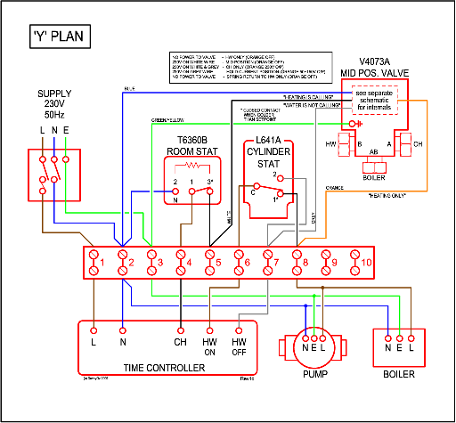
Hi I have just installed a Ferolli Tempra 30 to a new Y plan fully pumped system and followed the wiring diagram to the letter only to find that the diagram I require is not available.
After 4 days in the airing cupboard I managed to contact Ferroli who informed me that the 240v switch live required to feed the boiler terminal 2 from number 2 ( linked from 10 ) in the wiring center, as quoted in my ferroli diagram is for a previous boiler model ie Tempra 30 version 2 I appear to have version 3.
I have now been informed that Version 3 should have 2 x zero volt switching wires feeding the boiler to terminal 1 + 2 (at boiler) to replace the manufacturers link wire. ie switch wires via a zero volt room stat.
My question is which terminals do I feed the boiler from in the wiring centre as i believe the output from the 3 port valve orange, grey and white wires are 240v when calling for heat ( or am I wrong )
My sytem is as follows
ferroli Tempra 30 system boiler
SALUS RT200 HEATING ELECTRONIC TYPE ROOM STAT
Danfoss FP975 programmer
Honeywell V4073 3 port valve
SALUS-HOT-WATER-CYLINDER-TANK-STAT-CT100
Below is a link showing the diagram I followed omitting the 230v switch live as it suggested.
(page 26)
http://www.ferroli.co.uk/product_documentation/Domestic/Tempra_30_Installation.pdf
Many thanks for anyones help
Cheers
Andie
PS. I have trawled the net for a diagram but to no avail