Fuse keeps blowing

What is the black wire connected to?
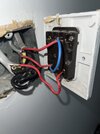
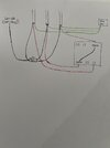
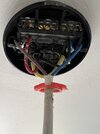
I will check again tomorrow but if I remember right there is a chock block that the blacks are connected to. There is 3 cables coming in. Each cable has red, black and earth. 2 reds are connected to com, & the other to L1. The blacks are in the chock block. Cant remember exactly so Ill need to check tomorrow. Never had an issue before, only since I reconnected 2 broken earths which I assume is what made me get a shock. I connected the earths to the switch earth not the back box earth where they were previously. Surely that wouldnt matter though would it? Its quite a tight space with all the wires, could anything have popped out whilst pushing it back in? Although how could that affect the switch in the other room?
 
Last edited:
  • Thanks
Reactions: CBW
Sponsored Links
Its quite a tight space with all the wires, could anything have popped out whilst pushing it back in? Although how could that affect the switch in the other room?
Could have popped out, Earth that’s loose could have touched a live, not sure about the other room.
 
Here is the light switch that keeps blowing the fuse all of a sudden.
 

Attachments

  • image.jpg
    image.jpg
    190.4 KB · Views: 78
The insulation is damaged on the red wire ,bottom right of pic. The blue bridge wire ,at the lower terminal appears to have a strand of bare copper wire sticking out that .
Both above needs attention. Can't see with any clarity the earth conductors ,are all of them connected together in a terminal on the metal
box ?
 
Sponsored Links
That can't be right, there are two switches, so there will be a feed likely looped to the two coms, and two outputs one to each lamp, but the blue loop seems to connect two red wires together, that does not make sense.
 
That can't be right, there are two switches, so there will be a feed likely looped to the two coms, and two outputs one to each lamp, but the blue loop seems to connect two red wires together, that does not make sense.
There is 2 switches as there used to be wall lights and ceiling rose. I removed the wall lights and pulled the cabling up through the walls and disconnected it from the light switch. Looking at it from the back, the left hand side of the pic is the switch I dont need but the right hand side of the pic is the ceiling light. How can I make this into just one switch? Can I remove the blue loop?
 
If I wanted to work it out I would start by marking each cable, felt pen would do, taking a photo so I can refer back, then putting them in a connector block so I can test safely and work out which wire is feed, which if any are neutrals, and which are earths, it will take some doing.
 
The insulation is damaged on the red wire ,bottom right of pic. The blue bridge wire ,at the lower terminal appears to have a strand of bare copper wire sticking out that .
Both above needs attention. Can't see with any clarity the earth conductors ,are all of them connected together in a terminal on the metal
box ?
Hi. There is enough length there I can cut and re-connect the damaged red. The blue I dont need as it used to be 2 sets of lights but I removed one. Yes the earths are all connected to the back box
 
Sorry can only guess and I have not read the whole thread, my guess is one of the blacks is not a neutral but a switches line. In the main in the UK the ceiling rose is used as a junction box, in other countries they use the switch back box as a junction box, there are pros and cons with each method, the use of down lights and the like resulted is a move from the ceiling rose to back box, so now either method can be used, but since red/black not brown/blue I would assume old system and ceiling rose used as junction box?

So the power goes the ceiling rose, then from that one to next rose, and then each rose has a pair of cables to the switch, it should be two reds, but in the main it was a red and black and the black should have been over sleeved with red, however often the sleeves are missing.

So if I was doing the job first I would look at ceiling rose to see how wired, and then use a connector block so I can test wires safely with my meter, I would find the permanent line, and put it in com. But from that point it would depend on what I had seen in the ceiling rose.
 
Thanks. Looking at the switch is there anything obvious that would have suddenly started causing the fuse to blow? Could it be something as simple as the bulb has blown?
 
The strand of wire I mentioned earlier,or if the red wire that has damaged insulation has bare copper exposed, either of which coming into contact with the earth conductors or the metal back box could cause a short circuit. However ,if the earth conductors were in fact not connected at the metal switch location ,nothing would blow a fuse as the earth conductors at the plastic switch location wouldn't actually be connected to earth.
Once you re instated them at the metal switch location,you now have a problem.
 
Your ceiling rose tells me switch back box used as junction box. I love my meter makes life easy it cost me £35 from the internet, and it has non contact volts range Testing for live.jpg OK there are cheaper meters, but the main problem with the DIY guy and meters is selecting wrong range and blowing fuse, can't really do that with the clamp type. Maybe £20 more expensive, but your less likely to blow it up.

Anyway since ceiling rose not used as junction box less likely a problem with blacks. My first test would be remove the blue link and see what happens.

I had never thought anyone would attempt DIY without a meter of some sort, sorry.
 

DIYnot Local

Staff member

If you need to find a tradesperson to get your job done, please try our local search below, or if you are doing it yourself you can find suppliers local to you.

Select the supplier or trade you require, enter your location to begin your search.


Are you a trade or supplier? You can create your listing free at DIYnot Local

 
Sponsored Links
Back
Top