Help with Nest instal.

Joined
3 Nov 2008
Messages
9
Reaction score
0
Location
Kent
Country
United Kingdom
So how hard can this be I tell my wife, darling it might look difficult but it’s just a simple case of swapping things over. Or so I thought

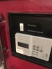
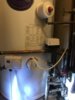
So I bought the Nest thermostat and heat link 3rd generation. Although I have a oil boiler it runs off a Honeywell programmer ST6400c, along with a room stat. I have a hot water tank with two valves, one on heating and one on the hot water. thought it might be a simple case of swapping it over but it looks far more complicated

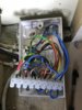
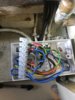
I have 5 wires into the controller, 2 of which are obviously live and neutral. The others go to 2-White 3- Black 4- Orange.


Any ideas of where these wires should go in the Heat Link would be greatly received. I also won’t lose face and my wife will think I can put my hand to anything.

Thank you
 
Sponsored Links
First of all, you can find out the function of the wires connected to your ST6400c from the diagram printed on it. L,N & E are straight forward. From memory I believe the others will be as below, but please check.

Terminal (4) Central Heating on (aka heating call for heat)
Terminal (3) Hot Water on (aka hot water call for heat)
Terminal (1) Hot Water off (aka hot water satisfied)

Unfortunately the wire colours you give don't help as the colours chosen would be the personal preferences of the original installer.

Once you have identified what the wires in each terminal do, they are simply moved to the Heat link terminals that have exactly the same function:

Nest.jpg


You will also need to add a link between the Heat link 'Live' terminal and the two common terminals 2 & 5

You can power the Nest Thermostat either by connecting its terminal T1 to T1 terminal at the Heat link, and the thermostat T2 terminal, to T2 at the Heat link. Or, by using a separate plug in power supply.

As the Nest also has the room thermostat functions built in, the existing room thermostat needs decommissioning. You can't just remove it as the heating wiring will remain open circuit and not operate. To do this, the existing thermostat cable is traced back to its origin. Note where the two live switching wires are connected and disconnected the old thermostat cable. Then add a wire link between where the two terminals where the live switching wires have just been removed from. If you need anymore help with this bit, post the details of your existing thermostat and wiring.

Instead of removing the old thermostat, if you were to leave it in place and set it to its maximum setting, that would allow the Nest to work, but is is not an ideal permanent solution.
 
Last edited:
Thank you so much, yes makes more sense now. I’ve checked the stat and it only has one neutral and a live and a switch live. I’m guessing I can just link these together and lose the neutral. Ideally i would like to utilise the same wires at the stat removing them from the 240v feed and use as 12v instead but I don’t know if these would run back to the boiler which is downstairs as the wiring junction box is upstairs by the stat.

Also was wondering if I could get the HW only working. The boiler has a separate switch on the panel (see picture). If I switch to HW only nothing happens, it has to be switched to CH and HW for the boiler to kick in. However once it fires up if I switch it over it will work on HW only. Can I do anything so it will work on the Heat Link

Thank you again for your help
 

Attachments

  • F6B58210-2A40-432C-83FA-8C20972FDDF8.jpeg
    F6B58210-2A40-432C-83FA-8C20972FDDF8.jpeg
    233.3 KB · Views: 359
You are right about the thermostat cable. Link the lives and lose the neutral. Unfortunately though often it doesn't really end up at the Heat link to allow it to be easily used to connect the Thermostat to the Heat link.

Sorry, I can't really help with the switch without knowing how it is wired in. I suspect that it was part of some earlier controls before the Honeywell and motorised valves were installed, so may not be functioning as originally intended. The new controls (Honeywell or Nest) should operate the heating and hot water separately so the switch shouldn't be necessary now, and isn't really compatible anyway.

From an electric point of view, the Nest is just a couple of switches, one for heating, and one for hot water exactly the same as the ST6400c is. So the Nest will work in the same manner as the ST6400c has been doing.
 
Sponsored Links
Thank you again, feel a lot more confident now and will install it tomorrow.
 
S_Plan.jpg
You may or may not have S plan, but you can see the colours used by the motorised valve, these are to some extent dependent on make and type, but there is a reasonably chance that using the colours of the wires from the motorised valve that you can identify what does what in the wiring centre, don't trust terminal numbers.
 
Thank you for your help, it’s up and running. Very pleased indeed.
However I don’t have HW only for some reason. I can live without this though at the moment.
That switch on the panel simply has two wires, white and an orange. Will try and track back to see what they do.
Anyway thank you again, great help
 
Did the Honeywell provide hot water control OK? if it did, the Nest should do exactly the same.
 
Actually it never worked on just HW but as I have two 2 port valves, one on the HW and one in CH I assumed I should be able to achieve HW only. It’s odd that if I flick that switch on the front plate to HW only when the boiler has cut in it will heat the HW only. But for some reason the boiler will not start up if the switch is flicked to HW initially
 
OK, thanks for the update. If it didn't work before, it won't now because you have swapped over the programmer 'like for like', so electrically speaking nothing has changed.

As you say, with two motorised valves it should be possible to have individual control of the heating and hot water, but only if it's wired up correctly. It appears that you may have had new controls fitted to an older system but the wiring not modified accordingly. Ericmark's diagram shows how it would normally be done.

You might find it a bit easier to understand how an S Plan (2 x two port motorised valves) would be wired, (without the original switch) by looking at the diagrams here. if you click on the links under 'S Plan' it will show you the various connections and what happens when.

In the diagrams, the pump is wired to be controlled by the motorised valves directly with the boiler, but some boilers now have a separate control circuit for the pump and have a set of terminals inside the boiler to connect the pump to instead.
 
Thank you Stem, that’s really interesting. I’m going to go through the junction box and work out what goes where, mark them and then compare against the wiring diagram.
As you said ultimately it’s just a selection of switches. NO or NC.
 
W_Plan_check.jpg
I have never used the W plan shown however reading it says W plan give priority, I see it has a change over micro switch in the HW motorised valve, not a clue why it is used? However may be your on a W plan not a S plan?
 
I have never wired a W Plan either. They are about as rare as hens teeth!

I was interested to see that you have posted a diagram of one using 2-port motorised valves. I seem to remember that I have only seen it with a three port valve that doesn't have a mid position, so heating and hot water at the same time is not an option.

The W Plan is designed so that if the heating and hot water are both calling for heat at the same time, the heating remains off until the hot water is satisfied. Once the hot water is heated, then the heating will come on. There isn't a manual switch required, the changeover happens automatically.

The switch as shown by jas100 below...

Capture.JPG


...looks to me to be more akin to the old gravity hot water / pumped central heating switch found on early controls.

Capture 1.JPG


I suspect that at one time there may have been a simple single channel timeswitch in place of the programmer controlling the boiler. With the switch in HW position the boiler would heat the hot water cylinder by natural gravity circulation. When heating was required the switch was moved to H/HW that would allow the pump to start and circulate water around the radiators as well.

Don't know why the switch would not have been disconnected when the motorised valves were added, there may be a reason, but unfortunately, my knowledge of oil boilers is limited and some do have the odd foible.......However the way jas100 describes it as working doesn't sound right to me. But, without knowing how the switch is connected to the rest of the wiring it is impossible to determine really.
 
So I’m working my way through this, I’ve removed the thermostat which originally connected between the brown and g/y with the red sleeve at the end of the connector. The black cable goes to the valve to the coil in the tank. The cable to the far right goes to the other valve and you can see the tank stat which has 5 cables. ????
 

Attachments

  • 9BD05ABD-FE47-4D24-A3FF-8B53B67B3B58.jpeg
    9BD05ABD-FE47-4D24-A3FF-8B53B67B3B58.jpeg
    235.1 KB · Views: 506
  • 4DF81F4D-8CB6-4C7C-A474-C2043C9ACB95.jpeg
    4DF81F4D-8CB6-4C7C-A474-C2043C9ACB95.jpeg
    270.3 KB · Views: 356
  • C65F6B58-A728-4215-8E99-275CEB93EA66.jpeg
    C65F6B58-A728-4215-8E99-275CEB93EA66.jpeg
    202.1 KB · Views: 323
It's difficult to see where some of the wires (cores) go, but here's my interpretation.
Counting the cables (from the second photo of the open junction box) from left to right
1. Tank stat (as labelled)
2. Programmer
3. Hot water zone valve (two port)
4. Mains power (LNE)
5. Heating zone valve (as you indicated)

Counting the terminals from top to bottom, I see their functions as:-
T1. N/C
T2. Green/yellow with red sleeve: Heating demand*
T3. Blue with red sleeve: Hot water is ON
T4. Hot water demand (drive ZV open)
T5. Permanent live
T6. Call for heat to boiler (oranges from ZVs)
T7. Earth
T8. Neutral
T9. Neutral

* the effect of this core going live is to open the heating valve, therefore it follows that, somewhere else in the building, the room stat's switch has interrupted it, so it won't be a feed directly from the timer/programmer.

So it appears that the cable number 2 already incorporates the roomstat's demand (ie it only goes live when the roomstat calls for heat AND the timer heating is ON). If that is the case then you can locate the Nest's heat link close to this terminals box. Even better, if cable 2 goes to the original thermostat's location first (and then on to the programmer) you can use its cores to power the Nest and locate the Nest where your old stat was (T1 and T2 on the heatlink!, not my terminal-ology).

I'm sure anyone with the minimum skillset to work on mains power will know what to do to achieve the above, but please in any case do not allow the T1 and T2 wires to run through this terminal box, remove them from this TB and extend them using a new TB to separate mains and low voltage dc.

Tip: Use 0.5mm2 cores into the heatlink, the terminals are particularly small, and you have to get two cores into some of them.
 

DIYnot Local

Staff member

If you need to find a tradesperson to get your job done, please try our local search below, or if you are doing it yourself you can find suppliers local to you.

Select the supplier or trade you require, enter your location to begin your search.


Are you a trade or supplier? You can create your listing free at DIYnot Local

 
Sponsored Links
Back
Top