Hive Multizone for ESI Three Zone System

Joined
6 Feb 2022
Messages
13
Reaction score
0
Country
United Kingdom
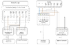
I have recently obtained the new Hive Mini system to replace my current ESI based three Zone (Ch1, CH2, HW) system.

I am looking for a little help on the electrical side which i think i have almost got, but there are a couple of wires I’m unsure on (everything seems to head to the main 3-zone ESI programmer), this differs from other posts for a ESI in a Redrow home (and/or they had no actual responses with answers - hence my post.

Current i have the following installed;
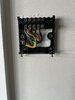
ESI3427B Programmer
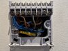
ESI ESRTERFW Thermostats (x2)

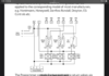
Currently I believe that the wires in the ESI Programmer are a near straight switchover;

N (4 Cables)
L (4 cables)
3 to 3 (HW ON)
4 top 4 (CH1 ON)

I’m not sure about cable 6 though which is CH2 (upstairs CH)

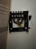
I have noticed that the Cable [4] in the programmer is a dif colour to that in the thermostat connection, so i assume this gone up to the electrical box on the hot water tank?

The upstairs thermostat also slightly confuses me, as it has a N, L 1,2,3

Which I think is straight swap but wouldn’t the [3] go to the downstairs programmer which goes nowhere?
 

Attachments

  • A4D5CDA5-4325-4720-9799-26BF700CD433.jpeg
    A4D5CDA5-4325-4720-9799-26BF700CD433.jpeg
    346.7 KB · Views: 413
  • 383FD2DF-3D89-4B2B-967C-C6574C639592.jpeg
    383FD2DF-3D89-4B2B-967C-C6574C639592.jpeg
    226.1 KB · Views: 247
  • Wiring Layout - Programmer.png
    Wiring Layout - Programmer.png
    89.8 KB · Views: 275
  • B2D53E6C-4A6E-4F4A-BB5F-2C1AD02697B2.png
    B2D53E6C-4A6E-4F4A-BB5F-2C1AD02697B2.png
    288.4 KB · Views: 262
Last edited:
Sponsored Links
Upstairs thermostat
 

Attachments

  • 0AB3429C-9B32-4077-8DF7-1978E64EBC71.jpeg
    0AB3429C-9B32-4077-8DF7-1978E64EBC71.jpeg
    343.5 KB · Views: 114
Last edited:
There are a few ways to split the heating, one is motorised valves, another is electronic TRV heads, also in my case more than one pump, but in the main where TRV heads are used there is no provision for motorised valves, and vie versa, there is no point both do the same thing.

So we have Drayton Wiser, your ESI3427B Programmer, and EPH who using different methods use motorised valves, EPH is as far as I know the only one where OpenTherm can be used with motorised valves, and seems you can have up to 10 zones with one thermostat as master and others all set as slaves. It seems OpenTherm does work with Drayton Wiser two port, but not recommended by Drayton, but Hive does not do a three channel version.

You can use a two channel and a single channel or combine both zones, the latter would seem the best idea since the Hive programmable TRV heads form the zones.

I assume an error in the wiring diagram and 4 = CH1 on not off. So like for like and wire at moment in 6 goes into 4 with the wire already there. This means both motorised valves open together.

The idea with Hive is the TRV heads send a demand for heat, however there is a 22°C maximum so wall thermostat needs to be in a room normally kept cool, normally the hall, if not using the Hive electronic TRV heads you could use the single channel hive as well and the duel channel, link between the two N and L and also a link on single channel L to Com, the wire going to 6 would now go to 3 on the single channel.

Personally I would not use all Hive TRV heads as rather expensive, I would select key rooms, and use much cheaper no linked eQ-3 or terrier i30 programmable TRV heads for other rooms. If hive is put in the hall, then it needs a TRV also in the hall, this allows quick recovery when front door opened and then it closes to nearly off before it can switch off the wall thermostat, it is important the wall thermostat does not exceed 22°C or the demand for heat stops working.

Be aware setting of the lock shield valves and TRV heads becomes critical. Hive is a simple on/off system, unlike most of the other smart thermostat systems, it is designed to allow the boilers own system to work and control the home using the return water temperature which is in turn controlled by the TRV heads, there should be a TRV head of some type on every radiator, and also a by-pass valve either built into boiler or external.
 
Sponsored Links
I assume an error in the wiring diagram and 4 = CH1 on not off. So like for like and wire at moment in 6 goes into 4 with the wire already there. This means both motorised valves open together.

Ah, so there maybe a couple of things here.

One - the hive mini is a thermostat approach, so I am replacing my existing ESI thermostats but i am not installing TRV’s currently, so i am straight swapping the ESI therms for Hive therms.

Two, the cable issue is interesting, I have just looked at the ESI manual and actually says two different things, one shows [4] as being CH1 on, and one shows it as CH1 OFF…

Which isn’t helpful.
 

Attachments

  • 637FD71F-94DD-44E6-AF6D-F0BDCB836BC8.jpeg
    637FD71F-94DD-44E6-AF6D-F0BDCB836BC8.jpeg
    89.3 KB · Views: 140
…if not using the Hive electronic TRV heads you could use the single channel hive as well and the duel channel, link between the two N and L and also a link on single channel L to Com, the wire going to 6 would now go to 3 on the single channel.

Apologies, this is the bit I'm not 100% on.

The cable on 6 (at the programmer) needs to go to port 3 at the receiver for CH2 (the single channel receiver).

Do i simply terminate the cable currently going to 6 with a choc block in at the dual channel side with the single channel side connected to 3.

I guess i also terminate /isolate the cable link currently between the programmer and CH1 thermostat currently?
 
i am not installing TRV’s currently
This I think means you need to fit multi-thermostats? Not sure on the legal position, but think there has to be multi-zones, does not matter what type of zone valve, and an electronic TRV is clearly a zone valve.

So
upload_2022-2-18_23-54-38.png
wired something like this, personally I would fit electronic TRV heads and use only one Hive, but that's up to you.
 
So i will be using the dual zone + single zone rather than TRV’s for a couple of reasons.

Ok, so i guess my remaining things are;

1. Replace the programmer with the Dual Channel Hive Receiver - connections as per above (straight forward).
2. CH1 thermostat (to be removed) has cabling that links L+1 (common) as it stands. Do i need to link [L] to [3] and remove the L to common link then “cap off” this connection (essentially passing it through for the hive to control)?
3. CH2 thermostat will be replaced as per the single channel receiver wiring (like for like) including the L to Com link.

4. The Current cable [6] in the programmer will not have anywhere to connect to on the new Dual Channel Hive, so do I connect this into [L] on the Dual Channel as the receiver manages on/off? Potentially removing the L to [1] Common link in the receiver?

Thank you for your help

Edit: For clarity, i don't want to perm remove anything as if we move we may revert back to the old system - at the least we want to have that option.
 
Last edited:

DIYnot Local

Staff member

If you need to find a tradesperson to get your job done, please try our local search below, or if you are doing it yourself you can find suppliers local to you.

Select the supplier or trade you require, enter your location to begin your search.


Are you a trade or supplier? You can create your listing free at DIYnot Local

 
Sponsored Links
Back
Top