Hive Multizone S Plan Wiring

Nothing will change at the boiler wiring terminals. It should remain exactly as it is.

Unfortunately there are so many ways to wire these systems up and installers don't all use the same wiring colours for the same thing, without knowing details of every wire and what is connected to it I can't be more specific. However one thing is certain, the boiler wiring doesn't need to be disturbed.

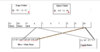
For the new motorised valve, the grey and orange wires will simply connect to the grey and orange wires of the existing motorised valve respectively. That will take care of the boiler control. Then the new valve is wired directly to the new Hive.

The new Hive N & L connect to the same 230V supply as the existing Hive.

Link Hive L to 1 Common.

Hive with 2 Zones.jpg
 
Sponsored Links
Hi Stem,

I did not get a chance to reply yesterday. I understand your point, the only thing which confuses me is one spare cable from the boiler. Please see attached is my existing wiring without any zones. Only one HIVE controlling the whole house.

Following is how my 5 core cable coming from the boiler.

Brown going to permanently live
Blue going to perminent N
Green going to Earth
Grey from boiler going to COM on the HIVE
Black from boiler going to CHon on the HIVE.

I know I am going around the circles but just wanted to be sure of it before I touch it.
 

Attachments

  • Without Zones.jpg
    Without Zones.jpg
    42.8 KB · Views: 230
Hive 'com' and 'on' are just an electrical switch. When the Hive turns the heating 'on' the two terminals are electrically connected together, but according to your drawing they are already permanently connected together at S/L effectively bypassing the Hive switch and meaning it would do absolutely nothing. So either the Hive is not working now, or you have drawn something wrong. Are you really sure that the Grey and Black cables are both connected together at S/L? I Would expect CH 'on' to go to S/L, and 'Com' to go to a permanent live, either at the boiler or via T4.

Hopefully you will see what I mean from the slightly different representation of your diagram below:

Drawing1 Model (1).jpg
 
Last edited:
No, Two separate cables coming from the boiler and not connected.

My only worry is with the zone valves one the cables will connect to orange, what will happen to the other?
 
Sponsored Links
The orange and grey wires are connected to a microswitch inside the motorised valve, when the valve opens, the microswitch operates, and the grey and orange wires are electrically connected together. This is what switches the boiler 'on'. As the existing motorised valve (Zone 1) will already be doing this, connecting the grey and orange wire of the new valve (Zone 2) to the grey and orange wire of the existing valve means that when the new valve opens it too will switch the boiler on.

No, Two separate cables coming from the boiler and not connected.

Sorry don't understand that! In your drawing, you show the black and grey wires connected together at S/L.

BTW I think you maybe getting the terms 'wires' and 'cables' confused. They are not the same thing.
 

DIYnot Local

Staff member

If you need to find a tradesperson to get your job done, please try our local search below, or if you are doing it yourself you can find suppliers local to you.

Select the supplier or trade you require, enter your location to begin your search.


Are you a trade or supplier? You can create your listing free at DIYnot Local

 
Back
Top