Hive Multizone wiring

Joined
13 Sep 2022
Messages
8
Reaction score
2
Country
United Kingdom
Hi,

I've just moved into a new build house & want to install hive thermostats.

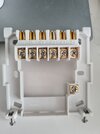
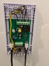
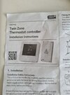
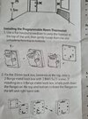
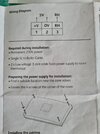
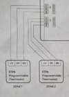
The boiler is an ideal logic esp1 35 with 2 heating zones.

The zones are controlled by esi RTP6 wired thermostats.

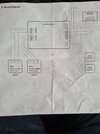
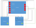
The attached picture shows the wiring centre diagram, but I'm unsure how to wire up the 2 hive receivers (both single channel)

Looking for any help or advice if possible.
 

Attachments

  • 20220915_093900.jpg
    20220915_093900.jpg
    245.7 KB · Views: 191
  • 20220915_095527.jpg
    20220915_095527.jpg
    141.7 KB · Views: 171
Sponsored Links
According to the diagram you posted, the existing thermostats operate using 5v. I would expect that the 5v is connected to the terminals marked +V and 0V, and RH is the control signal to start the heating. Unfortunately I don't have any info on these thermostats to confirm this. [RH is a term more frequently used overseas with A/C systems and means 'Red Heating' which is the connection used to power the heating function.]

Esi have many variants and change their products frequently so it might be hard to find documentation. If you can't find the details of the existing thermostat connections and what they actually do, someone competent with a multimeter should to test them to ascertain if my assumption is correct or not, before you proceed

Only if my assumption is correct, Hive terminals 1 & 3 can be used to switch the 5v, and the wires presently connected to +V and RH would be rerouted to them. The 0V wire will not be required and would be removed.

The Hive receiver also needs a 230V mains supply to provide it with operating power. This is connected to N & L and should come from the same 3A fused supply as the rest of the heating system, the N-E-L terminals at the bottom of the power supply PCB for example.

Under no circumstances make a link between terminals L and 1 as some Hive installations require. If you did you would be connecting mains voltage to something designed to work on 5v. The results would not be good.

You may find that someone has already done this before and can confirm the correct procedure.
 
Last edited:
Hi Stem, thanks for getting back to me.

If your assumptions are correct (I will obviously confirm this), is this what you are proposing?

I've not included wires to boiler or pcb power supply just to simplify things.
 

Attachments

  • image001.png
    image001.png
    34.9 KB · Views: 122
Sponsored Links
Not these ones. I originally thought the same, but they do a wired version.
I’ve looked on esI website and only one that exists with that model number is wireless. Are you getting confused about the receiver, which is wired?
 
I’ve looked on esI website and only one that exists with that model number is wireless. Are you getting confused about the receiver, which is wired?
I thought the same when we moved in as they only show wireless smart version.

It's only when looking at instructions that it becomes clear that these are wired. Esi confirmed the same via email.

Here's the manual that came with it:
 

Attachments

  • 20220915_172809.jpg
    20220915_172809.jpg
    271 KB · Views: 129
  • 20220915_172828.jpg
    20220915_172828.jpg
    263.8 KB · Views: 119
  • 20220915_172824.jpg
    20220915_172824.jpg
    247.5 KB · Views: 122
  • Thanks
Reactions: CBW
According to the diagram you posted, the existing thermostats operate using 5v. I would expect that the 5v is connected to the terminals marked +V and 0V, and RH is the control signal to start the heating. Unfortunately I don't have any info on these thermostats to confirm this. [RH is a term more frequently used overseas with A/C systems and means 'Red Heating' which is the connection used to power the heating function.]

Esi have many variants and change their products frequently so it might be hard to find documentation. If you can't find the details of the existing thermostat connections and what they actually do, someone competent with a multimeter should to test them to ascertain if my assumption is correct or not, before you proceed

Only if my assumption is correct, Hive terminals 1 & 3 can be used to switch the 5v, and the wires presently connected to +V and RH would be rerouted to them. The 0V wire will not be required and would be removed.

The Hive receiver also needs a 230V mains supply to provide it with operating power. This is connected to N & L and should come from the same 3A fused supply as the rest of the heating system, the N-E-L terminals at the bottom of the power supply PCB for example.

Under no circumstances make a link between terminals L and 1 as some Hive installations require. If you did you would be connecting mains voltage to something designed to work on 5v. The results would not be good.

You may find that someone has already done this before and can confirm the correct procedure.
Hi Stem, just wondering if you had chance to look at my proposed wiring diagram?

Planning on using .75mm twin & earth flex for everything. Should that be OK?
 
That all sounds good to me providing of course that my assumptions are correct. I thought the RTP6 were wireless too when I looked on line but as per the diagram you posted, yours are obviously not.

Like I said, Esi do seem to change things frequently.
 

Attachments

  • Capture.JPG
    Capture.JPG
    12.5 KB · Views: 88
Thanks @stem

Esi are quite confusing with their products. I emailed them today & there are at least 3 versions of the 6 series thermostat:

Mine, a wired wifi version that could just be plugged into my current backplate & the wireless version that you guys were referring to.

Just wired everything up for 1 zone & no luck unfortunately. Receiver powers up fine & responds to call for heating, but nothing happens at the boiler.

Back to the drawing board!
 
  • Thanks
Reactions: CBW
I wonder if it's the wiring centre that's incompatible with anything other than their 6 series thermostat.

If that's the case, I'd need to install a new one & wire the zone valves in etc I'm guessing?
 

DIYnot Local

Staff member

If you need to find a tradesperson to get your job done, please try our local search below, or if you are doing it yourself you can find suppliers local to you.

Select the supplier or trade you require, enter your location to begin your search.


Are you a trade or supplier? You can create your listing free at DIYnot Local

 
Sponsored Links
Back
Top