Hi,
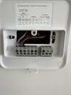
I am planning on replacing the two thermostats in my new build house that control the dual zone central heating. The thermostats are ESI ESRTP6C are connected to a wiring system that is connected to the combi boiler and two valves.
The thermostats have the following wires connected: +5V, 0V & RH.
The wiring system has the following: N, E, L & SL and +5V, 0V, RH (Zone 1) & +5V, 0V, RH (Zone 2)

I want to replace the upstairs thermostat and keep it connected via the existing wiring system. Looking at the Nest Installation information I am thinking of the following for Wiring System to Heat Link:
L > L
N > N
but I am unsure about the SL and RH on the wiring system.
Heat Link to Nest:
T1 & T2 to Thermostat
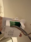
Will the wire (shown below) for the 5V thermostat be sufficient for the 12V required for the nest?

The downstairs thermostat will be plugged in so that one will not need T1 & T2 for power supply.
Any help will be much appreciated.
Thanks,
Rich
I am planning on replacing the two thermostats in my new build house that control the dual zone central heating. The thermostats are ESI ESRTP6C are connected to a wiring system that is connected to the combi boiler and two valves.
The thermostats have the following wires connected: +5V, 0V & RH.
The wiring system has the following: N, E, L & SL and +5V, 0V, RH (Zone 1) & +5V, 0V, RH (Zone 2)
I want to replace the upstairs thermostat and keep it connected via the existing wiring system. Looking at the Nest Installation information I am thinking of the following for Wiring System to Heat Link:
L > L
N > N
but I am unsure about the SL and RH on the wiring system.
Heat Link to Nest:
T1 & T2 to Thermostat
Will the wire (shown below) for the 5V thermostat be sufficient for the 12V required for the nest?
The downstairs thermostat will be plugged in so that one will not need T1 & T2 for power supply.
Any help will be much appreciated.
Thanks,
Rich


")


")