I've had a quick look and not a lot makes sense unfortunately, and it's wrong on many levels I'm afraid.
Only the Single channel Hive seems to have a mains supply to N and L. All the rest of the components with the exception of the Zone 2 valve which is connected to it, don't have any power supply to them. And the Zone 2 valve wouldn't work anyway as it doesn't have an neutral connected to an actual incoming neutral.
There also seems to be a blue wire (neutral?) just between the pump and HW motorised valve, but neither are connected to an actual neutral so neither the pump or the motorised valve would work.
All neutrals should be connected together [ie 3 x motorised valves, boiler and pump (unless the boiler has separate dedicated pump terminals more on this later)] and to an incoming supply neutral.
None of the terminals on any parts are labelled so who can say if they go where they should.
The Hive Dual Channel hot water live output [terminal 3] should go to the hot water cylinder thermostat, but I don't see it anywhere, and then to the HW motorised valve, but it goes instead to the "boiler thermostat"
Also what is "boiler thermostat"? There wouldn't be any connections to be made to the boiler thermostat, that is an integral part of the boiler control circuitry so wouldn't be any external connections to it whatsoever. I assume this is the boiler.
Also, most boilers control the pump directly from their internal PCB and have dedicated pump connection terminals for it. Not all, but you haven't given any details so I can't say, and if the pump isn't controlled by the boiler it would be connected to the same switched live and neutral as the boiler. Which it isn't.
On a plus point, terminal 4 from the dual channel hive goes to heating zone 1 motorised valve and provided it's connected to the motorised valve's live wire that's correct, and terminal 3 from the single channel hive goes to heating zone 2 motorised valve and provided it's connected to the motorised valve's live wire that's also correct.
You also have all of the motorised valve orange wires connected together, which is right but they don't go to the boiler which they should.
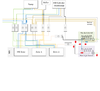
The basic concept is:
Hive dual channel terminal 3........>hot water cylinder thermostat......>hot water motorised valve live supply
Hive dual channel terminal 4........>Zone 1 motorised valve live supply
Hive single channel terminal 3........>Zone 2 motorised valve live supply
Both Hives, require L & N from the same 3A fused supply as the boiler [note, not all boilers require a permanent live but most do]
Same neutral connection to all 3 motorised valves and boiler
The orange and grey motorised valve wires control the boiler, so all grey MV wires are connected together to a permanent live and all orange MV wires are connected together to provide the switched live to fire up the boiler. So when any of the motorised valves is open, the boiler starts up.
It's not simple I'm afraid and can be costly to resolve if you get it wrong, from what you have posted, personally I feel you don't understand how the system works and would recommend that you engage the services of a professional to do this for you.