
where does pipe 5 go to after the ceiling, is it up into loft, whats attached to the other end?

You are using an out of date browser. It may not display this or other websites correctly.
You should upgrade or use an alternative browser.
You should upgrade or use an alternative browser.
Hot water going up the vent pipe
- Thread starter sotal
- Start date
I'm not quite sure, the ceiling in the airing cupboard isn't as high as the floor in the loft. So I'm not quite sure where it goes to up there, although I can try and have more of a dig round in the loft in the morning
Here is a picture of what I believe is the cold water feed (the curved pipe)

Here is a picture of what I believe is the cold water feed (the curved pipe)
have a rummage in loft to determine which is cold feed, still unclear on curved pipe, is a "tee" or "elbow" behind cylinder that it is curved into?
That pipe sounds like the cold feed for the domestic side of the cylinder, it realy needs to be 22mm all the way bag to the main cold water storage tank in loft.
no its just another issue that needs to be rectified at a later date. The vent & feed must be connected correctly into system to avoid a whole catalouge of related problems
The trouble is, sotal, there are so many things wrong that it's impossible to say with any certainty what's causing your current problem. If you manage to fix it with one change, then you'll still have a raft of things to deal with.
As heatingman has said, you should make certain changes to prevent long-term problems.
As far as I can make out, the pump, when running (at a speed setting that I can't see) is pumping some hot water from the boiler flow, via the cylinder coil, into the 15mm cold feed, and probably from there down the 22mm vent that's connected to the low pressure side of the pump.
With the heating on the sum of the resistances in all the pipework might reduce, or stop, this effect.
The basis of heatingman's suggestions is that the you connect the pipework in the following sequence, going in the direction of flow:
1. Vent.
2. Closed circuit cold feed.
3. Pump.
...and these should be within 600mm of each other (which they currently are).
Any other sequence is just wrong.
I would also get rid of the dead leg with the vent on top - all this will do is collect air until the point where the pump might air lock, until you remember to open the vent, and one day it will just scale up and be useless.
_____________________
Regarding the domestic cold feed, it's difficult to believe that someone would pipe it in 15mm, instead of 22mm (or 3/4") or even 28mm (or 1"), but people do crazy things. If it isn't already at least 22mm all the way from CSS to cylinder, then you need to change it.
_____________________
Also, why-oh-why-oh-why are the two thermostats connected with structural cable instead of flex, and why are they trailing around waiting to be trodden on and/or have things dropped on them? FPS change them to flex and get them off the floor, clipped where possible.
Also, FYI, putting PTFE on the threads of compression joints merely makes them harder to do up and harder to judge the right amount of torque too apply. It contributes nothing to making a water seal.
Looks to me like it was a grav hw system badly converted to fully pumped.
The cold feed is tee'd into the return from the cylinder and the OV pipe is tee'd in behind the pump. Id suggest the whole cupboard needs repiping. Dont really see the point in having both a gate valve and 15mm return from cylinder either.
The cold feed is tee'd into the return from the cylinder and the OV pipe is tee'd in behind the pump. Id suggest the whole cupboard needs repiping. Dont really see the point in having both a gate valve and 15mm return from cylinder either.
Thanks for the replies.
The pump is currently on speed setting 3.
I haven't had chance to tidy the wiring up yet but I will, and it isn't the floor, those floorboards are at waste height.
I was always taught to use PTFE tape for compression joints - If that's not what it's for - then what is it for?
I'm probably being thick but I'm struggling to get the concept of where the closed circuit cold feed is and where it should be. Is the closed circuit feed the 15mm pipe which is coming down to the T with the output flow from the cylinder?
So was heatingmans original instructions (to make a H) still correct, as I thought at the time he was assuming the 15mm at the from was teh domestic cold water?
Thanks for the replies.
The pump is currently on speed setting 3.
I was always taught to use PTFE tape for compression joints - If that's not what it's for - then what is it for?
Drop the pump speed to 2 for a start and see what differenc that makes.
PTFE is generally used on threaded joints rather than compressions. The olive does the job of sealing the joint. A couple of wraps of ptfe can be wound round the olive if you wanted to.
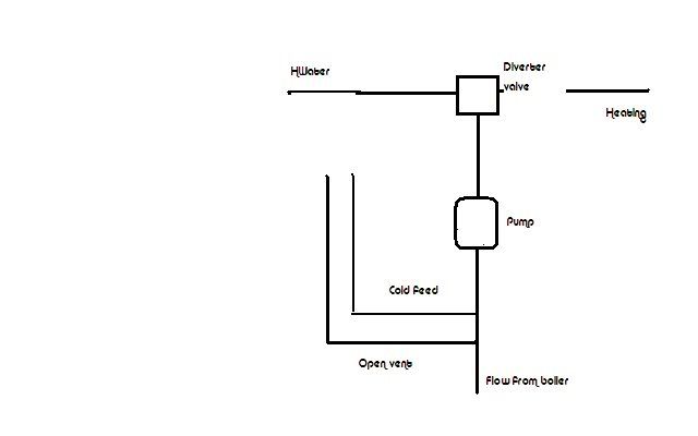
At the moment your closed circuit cold feed is entering the system on the return from cylinder (tee) it should be "Vent Feed Pump". If you alter ia my prev post it will vent itself and run a lot better. Also check the dry vent pipe, up and over header tank is at least 450mm. Level of water too top of pipe.
Heres a V basic diagram i just did in paint of what is being described.
I've just realised that the domestic cold water feed to the cylinder is 22mm, helps to look when it's not the middle of the night! So that bit is OK.
I now understand where the pipe should be, but I'm still a little unsure on heatingmans H shaped explanation.
Could I not just replace the T in the 15mm pipe with an elbow to take the return straight back down? Then bring the cold water feed round and T into the horizontal pipe below the pump? Any chances of a pic of the H layout?
Also the 15mm return from the cylinder - will that be a problem or is that fine to be like that?
DIYnot Local
Staff member
If you need to find a tradesperson to get your job done, please try our local search below, or if you are doing it yourself you can find suppliers local to you.
Select the supplier or trade you require, enter your location to begin your search.
Please select a service and enter a location to continue...
Are you a trade or supplier? You can create your listing free at DIYnot Local
Similar threads
- Replies
- 0
- Views
- 2K
- Replies
- 1
- Views
- 8K
- Replies
- 5
- Views
- 5K