Faced with this problem I found lots of confusing and incomplete information on various sites.
So this note gives the benefit of my experience in getting this cylinder stat working.
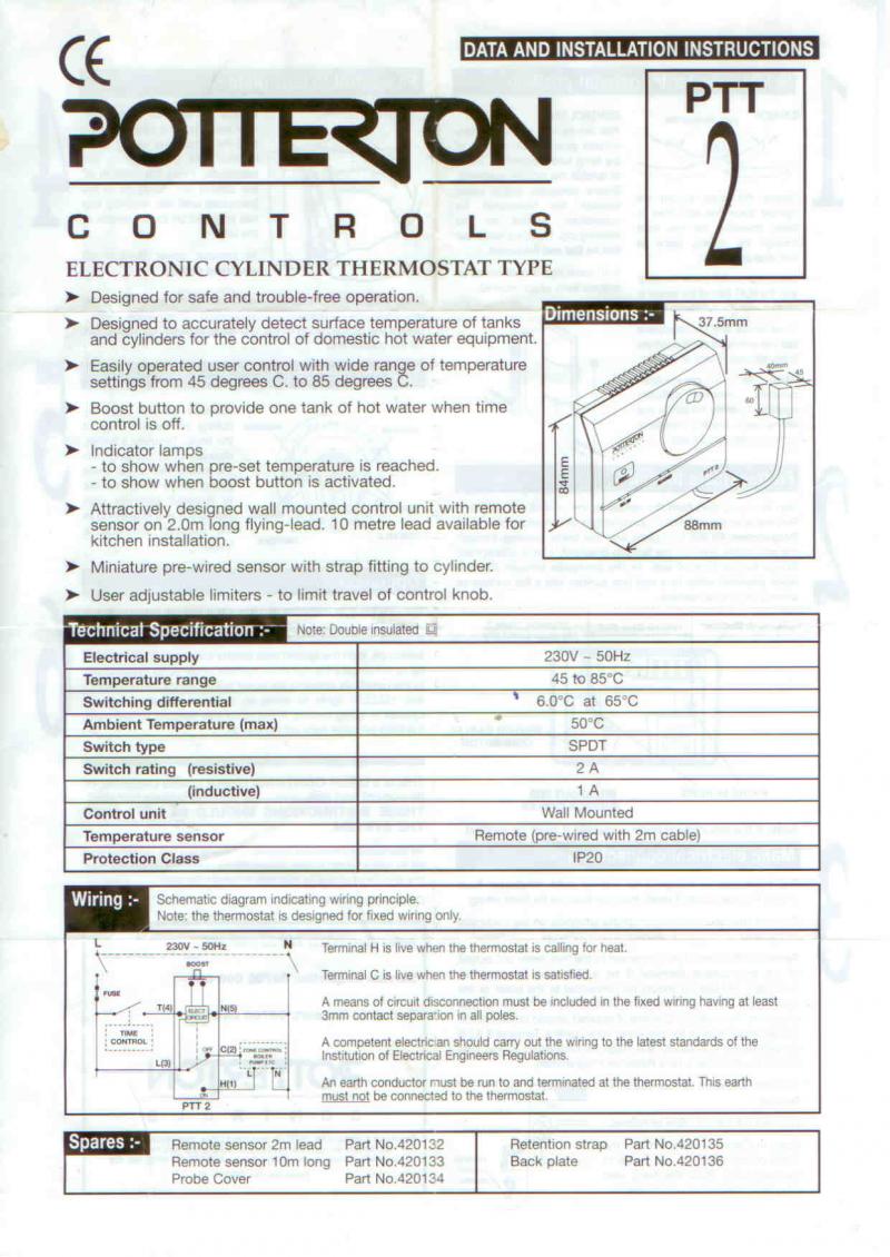
Most commonly people will be replacing a bi metal mechanical thermostat which sits on the cylinder with this electronic, remotely controlled stat.
The PTT2 has a much more sensitive response than most bi metal stats. Typically the PTT2 will cut out at the temperature you set and cut back in when the temperature falls by 5 or 6 degrees centigrade. A bi metal stat will need a much bigger temperature drop before it cuts back in.
So if you set a low temperature (say 45 to 50 degrees) to save fuel then with a bi metal stat the water will run cold before it has time to be reheated. To avoid this problem with a bi metal stat you will need to set a higher temperature (60 degrees plus) and you will use/waste more energy.
The PTT2 avoids this problem.
The PTT2 has five connections. This means you will need to run a 2 core and earth wire (Brown, Blue, Earth) plus a three core and earth wire (Red, Blue, Yellow, Earth) to the stat. To distinguish the two blue wires, strip one wire back at each end and sleeve it in red (say).
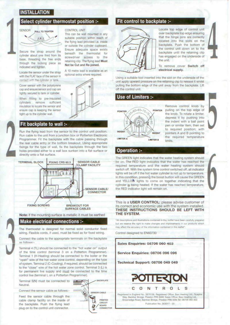
The lead from the sensor to the stat can be fed into the stat on the surface or from the rear if the stat is mounted on a 25mm box.
The sensor can be strapped to the HW cylinder or if the cylinder has the foam moulded to it, cut a hole slightly bigger than the sensor, push the sensor against the cylinder, fill round with foam insulation cut from pipe insulation, push down and seal over with brown parcel tape!
The PTT2 fitting instructions are at the end of this note.
Now for the wiring.
The PTT2 terminals are labelled 1 to 5 (left to right), connections are
Terminal Symbol Function Wire Connect to
1 H HW On/Call Blue with sleeve Terminal 8
2 C HW Off/Satisfied Yellow Terminal 7
3 L Permanent Live Red Terminal 1
4 TL HW on Call from Programmer/Timer Brown Terminal 6
5 N Permanent Neutral Blue Terminal 2
At the Stat both earth wires should be sleeved and connected to the earth terminal in the 25mm box. In the Wiring Centre both earth wires should be sleeved and connected to Terminal 3.
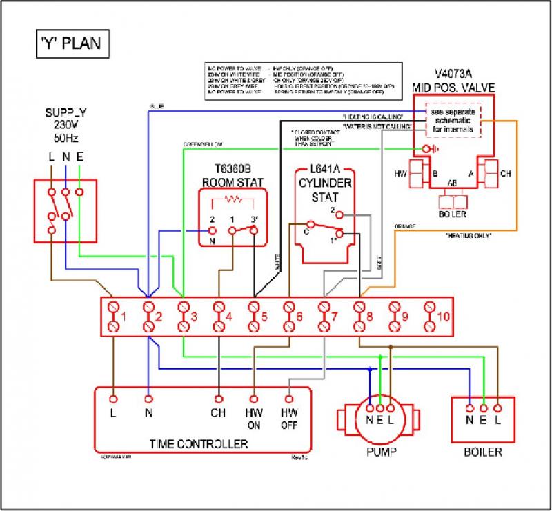
The Connect to Terminal Numbers are those in the standard Y plan Wiring Centre with a mid position valve. These are shown in the diagram below.
If you have a different Wiring Centre set up, then you can deduce the correct terminals by choosing
Blue with sleeve (H) connects to the terminal which connects via the orange (usually) wire to the mid position valve.
Yellow (C) connects to the terminal which connects via the grey (usually) wire to the mid position valve.
Red (L) connects to the terminal which has a wire running to the live on the fused connection unit supplying power to the boiler.
Brown (TL) connects to the terminal which has a wire connecting to the HW Call terminal on the programmer/timer.
Blue (N) connects to the terminal which has a wire running to the neutral on the fused connection unit supplying power to the boiler.
How it works
If timer is switched on for water heating then if the temperature not satisfied the water will heat (green light on Stat) until it is hot enough (red light on Stat). If the water temperature falls (say through use) cycle will repeat.
If timer is not switched on for water heating, no lights will show.
If timer is switched on for water heating the boost button has no effect – as it should because either the water is hot enough or it is already heating!
If timer is not switched on for water heating and you push the boost button, yellow and green lights will show and a tank of water will be heated at which point the red light will show.
So this note gives the benefit of my experience in getting this cylinder stat working.
Most commonly people will be replacing a bi metal mechanical thermostat which sits on the cylinder with this electronic, remotely controlled stat.
The PTT2 has a much more sensitive response than most bi metal stats. Typically the PTT2 will cut out at the temperature you set and cut back in when the temperature falls by 5 or 6 degrees centigrade. A bi metal stat will need a much bigger temperature drop before it cuts back in.
So if you set a low temperature (say 45 to 50 degrees) to save fuel then with a bi metal stat the water will run cold before it has time to be reheated. To avoid this problem with a bi metal stat you will need to set a higher temperature (60 degrees plus) and you will use/waste more energy.
The PTT2 avoids this problem.
The PTT2 has five connections. This means you will need to run a 2 core and earth wire (Brown, Blue, Earth) plus a three core and earth wire (Red, Blue, Yellow, Earth) to the stat. To distinguish the two blue wires, strip one wire back at each end and sleeve it in red (say).
The lead from the sensor to the stat can be fed into the stat on the surface or from the rear if the stat is mounted on a 25mm box.
The sensor can be strapped to the HW cylinder or if the cylinder has the foam moulded to it, cut a hole slightly bigger than the sensor, push the sensor against the cylinder, fill round with foam insulation cut from pipe insulation, push down and seal over with brown parcel tape!
The PTT2 fitting instructions are at the end of this note.
Now for the wiring.
The PTT2 terminals are labelled 1 to 5 (left to right), connections are
Terminal Symbol Function Wire Connect to
1 H HW On/Call Blue with sleeve Terminal 8
2 C HW Off/Satisfied Yellow Terminal 7
3 L Permanent Live Red Terminal 1
4 TL HW on Call from Programmer/Timer Brown Terminal 6
5 N Permanent Neutral Blue Terminal 2
At the Stat both earth wires should be sleeved and connected to the earth terminal in the 25mm box. In the Wiring Centre both earth wires should be sleeved and connected to Terminal 3.
The Connect to Terminal Numbers are those in the standard Y plan Wiring Centre with a mid position valve. These are shown in the diagram below.
If you have a different Wiring Centre set up, then you can deduce the correct terminals by choosing
Blue with sleeve (H) connects to the terminal which connects via the orange (usually) wire to the mid position valve.
Yellow (C) connects to the terminal which connects via the grey (usually) wire to the mid position valve.
Red (L) connects to the terminal which has a wire running to the live on the fused connection unit supplying power to the boiler.
Brown (TL) connects to the terminal which has a wire connecting to the HW Call terminal on the programmer/timer.
Blue (N) connects to the terminal which has a wire running to the neutral on the fused connection unit supplying power to the boiler.
How it works
If timer is switched on for water heating then if the temperature not satisfied the water will heat (green light on Stat) until it is hot enough (red light on Stat). If the water temperature falls (say through use) cycle will repeat.
If timer is not switched on for water heating, no lights will show.
If timer is switched on for water heating the boost button has no effect – as it should because either the water is hot enough or it is already heating!
If timer is not switched on for water heating and you push the boost button, yellow and green lights will show and a tank of water will be heated at which point the red light will show.