

So I live in a new build and the house builder installed some additional wiring up to 2 blank faceplates which I’ve attached a photo of the first of the 2 blanks. They are above the kitchen cabinets with the idea being if I ever wanted to install lights under the cabinets they said all I need to do is put A 3 gang switch in place of the 2 gang there at the moment for the 2 ceiling lights.
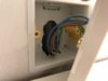
I have now installed some Philips Hue light strips under my cabinets which I have plugged into the normal sockets (taking up the only 2 spares I had - wife no so keen ) which means the wires come down and are visibleas is the large transformer plugs. Plugging them in at the top hidden away is the perfect solution. So I have got 2 single unswitched sockets to replace the blanks with which I’m fairly confident with - they are literally a strait swap and wires the same as the current blank faceplates. Attached a photo behind the first blank the wire comes to from the switch and then it feeds the 2nd blank.
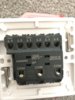
What I’m not so sure about is the switch going from 2 gang to the 3 gang (attached). From what I see behind the current switch (attached) are 2 feeds coming into it?? Not sure what this is for... and the feed is looped across 3 ports called L1 L2 and L3 which on the new switch I think would be the COM ports? It’s a one way switch no other switches control these lights. The 2 single love wires I assume are for the 2 current ceiling lights. So I think I just wire as is with the lights in the L1 ports on the reverse of the new switch including the unconnected wire that runs up to the blanks I’m replacing then have the feed some into switch 1 and out from switch 3s COM looped in the middle Switch?
At the moment there’s is 2 separate connector blocks both with neutrals in. Guessing I’d squeeze in the new neutral beside the other 2 coming from the ceiling light wires. There’s also an earch behind there thats connected to a block and not actually earthed and another earth including the one from the unconnected wire they’ve already earthed to the metal box. I think it’s looped up with the 2 earth wires from the ceiling lights.
I know it’s long winded but am I on the right track?
Also I do know your not supposed to install a 13a socket on a lighting circuit but the hue lights have a 12v transformer style plug that can’t be changed for a 5v one. The sockets are nearly ceiling level hidden up top of the cabinets so unlikely anyone would use for anything high powered and I do plan on labelling the sockets 5A MAX LIGHTING.
If I get any of it wrong what’s the worst that could happen? Would it just trip the breaker?
I have now installed some Philips Hue light strips under my cabinets which I have plugged into the normal sockets (taking up the only 2 spares I had - wife no so keen
) which means the wires come down and are visibleas is the large transformer plugs. Plugging them in at the top hidden away is the perfect solution. So I have got 2 single unswitched sockets to replace the blanks with which I’m fairly confident with - they are literally a strait swap and wires the same as the current blank faceplates. Attached a photo behind the first blank the wire comes to from the switch and then it feeds the 2nd blank.What I’m not so sure about is the switch going from 2 gang to the 3 gang (attached). From what I see behind the current switch (attached) are 2 feeds coming into it?? Not sure what this is for... and the feed is looped across 3 ports called L1 L2 and L3 which on the new switch I think would be the COM ports? It’s a one way switch no other switches control these lights. The 2 single love wires I assume are for the 2 current ceiling lights. So I think I just wire as is with the lights in the L1 ports on the reverse of the new switch including the unconnected wire that runs up to the blanks I’m replacing then have the feed some into switch 1 and out from switch 3s COM looped in the middle Switch?
At the moment there’s is 2 separate connector blocks both with neutrals in. Guessing I’d squeeze in the new neutral beside the other 2 coming from the ceiling light wires. There’s also an earch behind there thats connected to a block and not actually earthed and another earth including the one from the unconnected wire they’ve already earthed to the metal box. I think it’s looped up with the 2 earth wires from the ceiling lights.
I know it’s long winded but am I on the right track?
Also I do know your not supposed to install a 13a socket on a lighting circuit but the hue lights have a 12v transformer style plug that can’t be changed for a 5v one. The sockets are nearly ceiling level hidden up top of the cabinets so unlikely anyone would use for anything high powered and I do plan on labelling the sockets 5A MAX LIGHTING.
If I get any of it wrong what’s the worst that could happen? Would it just trip the breaker?
Attachments

Last edited:

 hopefully makes sense