

Hello,
I'd like to fit a voltage free wireless thermostat (Horstmann HRT4-ZW and ASR-ZW receiver) to my ten year old oil combination boiler (Worcester Heatslave 12/14). I do not currently have a thermostat, just a programmer on the boiler and TRVs on the radiators.
The boiler manual says "the thermostat must be suitable for use on mains voltage". From my research on this forum, I think it's okay to use a voltage free thermostat here, I just need to wire it differently to the boiler instructions for wiring a mains voltage thermostat.
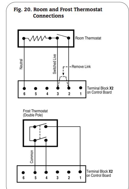
For a mains voltage thermostat the boiler instructions say to wire the boiler terminal block as follows:
(What I think is) return live on 2.
Switched live on 3.
Remove the link between 2 and 3
Neutral on 6.
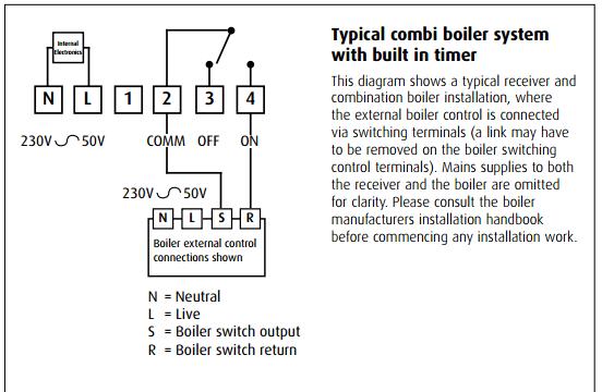
The thermostat instructions say:
Switched live on 2.
Return live on 4
Separate live and neutral
So would I wire this as:
Boiler 3 to stat 2
Boiler 2 to stat 4
Separate live and neutral
If so, what's the best way to get a live to this thermostat? Would I have to run 4-core cable (1.0mm heat protected?) to run another live from the boiler or power the receiver externally?
I appreciate this is what some refer to as "another thermostat wiring question", but I have read a lot of posts on here and I would really appreciate running it past a few of you friendly chaps as a sanity check")
I'd like to fit a voltage free wireless thermostat (Horstmann HRT4-ZW and ASR-ZW receiver) to my ten year old oil combination boiler (Worcester Heatslave 12/14). I do not currently have a thermostat, just a programmer on the boiler and TRVs on the radiators.
The boiler manual says "the thermostat must be suitable for use on mains voltage". From my research on this forum, I think it's okay to use a voltage free thermostat here, I just need to wire it differently to the boiler instructions for wiring a mains voltage thermostat.
For a mains voltage thermostat the boiler instructions say to wire the boiler terminal block as follows:
(What I think is) return live on 2.
Switched live on 3.
Remove the link between 2 and 3
Neutral on 6.
The thermostat instructions say:
Switched live on 2.
Return live on 4
Separate live and neutral
So would I wire this as:
Boiler 3 to stat 2
Boiler 2 to stat 4
Separate live and neutral
If so, what's the best way to get a live to this thermostat? Would I have to run 4-core cable (1.0mm heat protected?) to run another live from the boiler or power the receiver externally?
I appreciate this is what some refer to as "another thermostat wiring question", but I have read a lot of posts on here and I would really appreciate running it past a few of you friendly chaps as a sanity check