Minimal voltage in old ring mains

Joined
4 Feb 2012
Messages
41
Reaction score
0
Location
Middlesex
Country
United Kingdom
Hi
I am confused!
Whilst decorating, I found buried in the wall, two mains size cables (each with red, black and earth cables) that are simply terminated with insulation tape.
It looks like they were part of a ring mains and were probably both connected to a mains socket.

I tested it with my volt meter and there were no readings except when connecting any of the red, black or earth leads of the first cable in turn to the earth of the second cable, but which then registers just 0.8 volts (0.8 with voltmeter set at 200V range). No reading comes from red or black of the second cable.

I just dont understand what would cause that? Is there some form of induced current?

Any advise much appreciated - thanks - Graham
 
Sponsored Links
Your meter is set to AC, right?

Yes, it could be induced or coupled from another circuit. Or it could be DC leakage through bad insulation. This is not unusual. You see it because your meter has such a high input impedance. (Do the maths!)

As an experiment, see if you can measure a similar voltage at a switched-off light fitting.
 
Thanks for your reply.
Yes I do have the meter set to AC.
Afraid I am too thick to do the maths as dont understand what the meter impedance means!
I tried it on a light bayonet socket as suggested by running the meter from the two terminals in turn to a hot water pipe, but no reading. But of course that would be a separate circuit anyway.

My main question I guess is, will it be ok just to put back the insulation tape and bury in the wall as it was? Or should I terminate into a small box to protect it? Or something else?

Thanks Graham
 
Since they have been there without causing any obvious problem you could terminate them in a more suitable and better insulated way.

That said identifying where they go to would be the better option. They may have been "dead" when you measured the voltages but may at other times become live due to a time switch, off peak supply or other switch.

The impedance of the meter used does affect the voltage on the wire being measured. When the meter measure the voltage it takes some current and this causes a voltage drop across the impedance along the cable between the probe and the source of the voltage.

The impedance in the meter and the impedance of the voltage source form a voltage divider, if they are equal the voltage indicated is half the voltage at the source of the voltage.

An electronic ( digital ) meter has a very high impedance and when measuring from a low impedance source such as a wire direct to the Live terminal in the fuse box the voltage shown is 99.99999% percent of the actual voltage.

If the voltage is coming from the Live via capacitive coupling between two adjacent but not connected wires then the source is high impedance and the ratio of that impedance and the impedance of the meter will affect the value shown on the meter.
 
Sponsored Links
Afraid I am too thick to do the maths as dont understand what the meter impedance means!

Somewhere there is 240V. This goes through an impedance R to reach your wire, and then through the impedance of your meter to ground. R and the impedance of your meter form a potential divider, and from the 0.8V that you measure you can compute R. If the impedance of your meter is 1 MOhm, then R = 1e6 x 240 / 0.8 = 300 MOhm.

300 M could be a DC insulation resistance, or it could be capacitive or inductive coupling.

At frequency f, the impedance of a capacitor is 1 / (2 pi f C). So in this case, a 300 M impedance at 50 Hz could be explained by a capacitance of about 10 pF. That could be caused by two wires approximately 1mm apart, 1mm in diameter, and 1m long.

Observing voltages of this sort is very common.
 
Thanks. None the wiser as far as the technical stuff is concerned. But pleased to hear it is very common.
So will seal up and put back where they came from

Thanks for the advice
 
You really should find both ends and ensure they are not connected to anything and could become live. Unknown cables buried in walls can kill.
 
Hi
Thought I should update. Interestingly, having taken the readings more carefully, I find that when connecting to the earth cable (no inner insulation) I get a reading of 0.8volts. From the neutral I get 0.7volts and from the live cable I get 0.6 volts.
In each case the other terminal of the meter is connected to earth on the second cable.
I am guessing this variation arises based on how near each of these individual disconnected cables are from the live cable they are receiving an induced current from.
Interesting - Graham
 
Without knowing to where the "earth" in the second cable is connected those readings are almost meaning less.

You need to measure between a known "earth" and the wires to get a set of meaning full results.

If you measure the voltage between two live wires the meter will show almost zero even though both probes are at 230 volts above ground.

If the earth in the second cable is not connected to anything when you measure between it and a live wire the meter is likely to show a voltage close to zero. This because the current through the meter will pull the unconnected "earth" wire up to 230 volts.
 
Good point
I have connected to a known earth but I do get similar results of 0.6V, 0.4v and 0.3v .
Graham
 
Good point ... I have connected to a known earth but I do get similar results of 0.6V, 0.4v and 0.3v .
Those reading are all 'effectively zero'. As has been explained, what you are seeing is just slight 'pick up' from other cables etc. - which is to be expected, and nothing to be concerned about. As everyone has said, the best/proper course would be to find the other end of the cable, but ..... !

Kind Regards, John
 
I still like to carry an old fashioned moving needle low impedance meter.
 
I still like to carry an old fashioned moving needle low impedance meter.
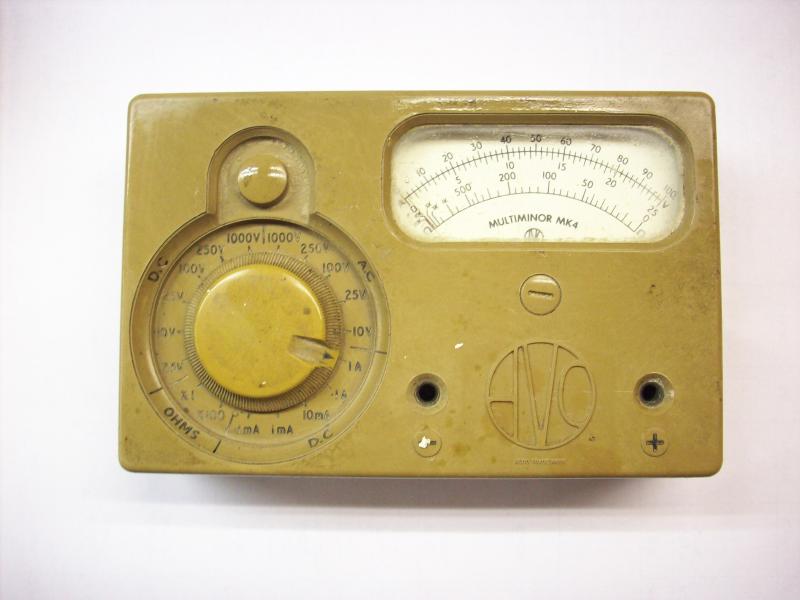
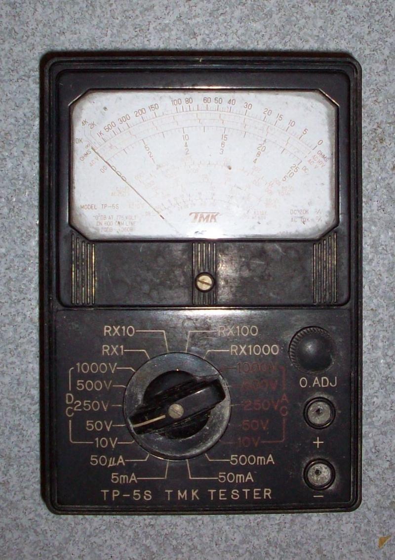
Very sensible - and, as I've mentioned before, I still even keep my 'old faithfuls' (with the emphasis on the 'old' - I've had both of these for ~50 years!) in my drawer:
Mind you, in the context we're talking about, one still probably has to use a fairly lowish voltage range to 'completely kill' many of these voltages due to stray capacitive coupling. Many such meters, like the AVO above, were about what used to be described as "10 kΩ/V" (reflecting the underlying 100 μA meter movement), meaning that on the 250V range it would have an input impedance of about 2.5 MΩ. The second meter above has a 50 μA movement and therefore is probably about 5 MΩ on its 250V range.

Kind Regards, John
 
Thanks for the reassurance. Finding the other end would be very difficult and inolves picking up newly laid wooden flooring etc.
Many thanks for the help
 

DIYnot Local

Staff member

If you need to find a tradesperson to get your job done, please try our local search below, or if you are doing it yourself you can find suppliers local to you.

Select the supplier or trade you require, enter your location to begin your search.


Are you a trade or supplier? You can create your listing free at DIYnot Local

 
Sponsored Links
Back
Top