
You are using an out of date browser. It may not display this or other websites correctly.
You should upgrade or use an alternative browser.
You should upgrade or use an alternative browser.
Programmer wiring
- Thread starter BC98
- Start date
D
Deleted member 267285
Which instructions have you followed? There’s 2 diagrams there.the oil boiler only fires for CH when HW is on if you go by the instructions for new programmer
You only need L N, heating no, hot water no and hot water off.
I went by the diagram at the bottom so I guess that’s correct for a programmer that controls heating and hot water but when you leave hot water off and just turn on heating the oil boiler wont fire but other way round and it does fire so I’m confused
It appears you may have a gravity system, with the wiring set up as in this thread...

 www.diynot.com
What is the model of your new programmer?
Some have the option of a 'gravity' mode, some don't.
Honeywell st669 to st9400c
Hi wondering if someone can help me This was my existing wiring. What I have read there at no links needed. I wired the st9400c As the following However my central heating doesn’t come unless the water is on. The previous set up was Central heating can be on without water And vice...
www.diynot.com
What is the model of your new programmer?
Some have the option of a 'gravity' mode, some don't.
It looks like the LP522 has a gravity mode option on the rear...New programmer is Drayton LP522 I believe
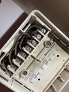
It's difficult to fully see the wiring in your programmer, so it will be up to you to confirm how it is connected up.
As I see it, there appears to be:
Two blue wires in N, these would move to N on the LP522.
L to L
Yellow (oversleeved red) in terminal 8 to H/W ON (3)
Red in terminal 3 to C/H ON (4)
There won't be a need for any further link wires, as the gravity mode of the LP522 should take care of the switching.
But again, as earlier, you will need to confirm your existing wiring looks something like...
Last edited:
Please let us know if it works!Ok excellent thank you so much I appreciate the help from you and everyone else
I’ll update if I need anymore help lol
")
- Joined
- 27 Jan 2008
- Messages
- 28,938
- Reaction score
- 3,541
- Location
- Llanfair Caereinion, Nr Welshpool
- Country

There seems to be a connection to DHW N/C so to me that points to Y Plan. With the Y Plan the motorised valve doubles as a relay for central heating, but DHW goes direct to boiler 
 so if one of the V3 micro switches stick in the motorised valve then often you can get it so the CH will only work when the DHW is called for, often latching the motorised valve to the bleed position will allow CH to work, but then during the summer when DHW is called for the radiators get slightly warm, so only a temporary cure.
What I am saying possibly you have wired it up correctly, and in the past some one may have latched the bleed lever on the motorised valve and you have knocked the lever unlatching it, so the fault has become apparent.
Question must be what motorised valves if any have you got? In general C Plan no motorised valves, S Plan two x two port valves, and Y and W Plan three port valve, the Y plan the three port valve has a mid position, the W plan DHW takes preference, the W Plan is normally within the boiler where stored DHW is very small.
There are exceptions, I have a C Plan with two x two port valves and two pumps plus relays, but that is because I have a main house and a granny flat, heated from one boiler, unlikely to find that in most homes.
So job one work out what Plan you have, oil boilers tend to use C or Y plan so when it switches off it can cool by heating DHW.
so if one of the V3 micro switches stick in the motorised valve then often you can get it so the CH will only work when the DHW is called for, often latching the motorised valve to the bleed position will allow CH to work, but then during the summer when DHW is called for the radiators get slightly warm, so only a temporary cure.What I am saying possibly you have wired it up correctly, and in the past some one may have latched the bleed lever on the motorised valve and you have knocked the lever unlatching it, so the fault has become apparent.
Question must be what motorised valves if any have you got? In general C Plan no motorised valves, S Plan two x two port valves, and Y and W Plan three port valve, the Y plan the three port valve has a mid position, the W plan DHW takes preference, the W Plan is normally within the boiler where stored DHW is very small.
There are exceptions, I have a C Plan with two x two port valves and two pumps plus relays, but that is because I have a main house and a granny flat, heated from one boiler, unlikely to find that in most homes.
So job one work out what Plan you have, oil boilers tend to use C or Y plan so when it switches off it can cool by heating DHW.
Yes, there is - which connects to C/H N/O.There seems to be a connection to DHW N/C
And also DHW N/O, I believe connects to Live.
Hence gravity, but also...
as earlier, you will need to confirm your existing wiring looks something like...
Last edited:
- Joined
- 27 Jan 2008
- Messages
- 28,938
- Reaction score
- 3,541
- Location
- Llanfair Caereinion, Nr Welshpool
- Country
There do seem to be three versions of C Plan, 

 each one uses gravity, but first no DHW temperature control, second summer DHW temperature control and it also allowed boiler to be active 24/7 without it cycling all the time, and the last also gives winter DHW temperature control.
I have the first system. to combine the programmer and thermostat there are two methods, one needs volt free contacts shown here with Nest the other uses a software fix inside the controller so two independent supplies for pump and boiler this is done with the Hive system.
I have not done a truth table for the second two variants of the C Plan, never needed to, so not looked into it. Had enough problems getting the first version with twin pumps to work, had to add motorised valves and relays to stop reverse flow and get the two outputs from motorised valve one to boiler and one to pump, hence two relays.
But no variant seems to use the N/C contact. Only the Y Plan seems to use the N/C contact as with the Y Plan DHW is default, and the valve needs powering to stop it.
I have never seen a link N/C DHW to N/O CH before, and can't off hand work out why, unless already using a combined thermostat/programmer as shown with Nest Gen 3 wiring where Com is output rather than input, but seems likely if no motorised valves then it is C Plan, but as yet don't know answer to that.
As you say old programmers were considered as 16 option, a cheat as the counted off, but this was reduced to 10 for C Plan often with both a dip switch and a mechanical stop. You could not have CH without DHW, I have the same today with Nest Gen 3, summer DHW is electric from solar panels, winter it is from the oil fired CH boiler, no way to turn it off.
each one uses gravity, but first no DHW temperature control, second summer DHW temperature control and it also allowed boiler to be active 24/7 without it cycling all the time, and the last also gives winter DHW temperature control.I have the first system. to combine the programmer and thermostat there are two methods, one needs volt free contacts
shown here with Nest the other uses a software fix inside the controller so two independent supplies for pump and boiler this is done with the Hive system.I have not done a truth table for the second two variants of the C Plan, never needed to, so not looked into it. Had enough problems getting the first version with twin pumps to work, had to add motorised valves and relays to stop reverse flow and get the two outputs from motorised valve one to boiler and one to pump, hence two relays.
But no variant seems to use the N/C contact. Only the Y Plan seems to use the N/C contact as with the Y Plan DHW is default, and the valve needs powering to stop it.
I have never seen a link N/C DHW to N/O CH before, and can't off hand work out why, unless already using a combined thermostat/programmer as shown with Nest Gen 3 wiring where Com is output rather than input, but seems likely if no motorised valves then it is C Plan, but as yet don't know answer to that.
As you say old programmers were considered as 16 option, a cheat as the counted off, but this was reduced to 10 for C Plan often with both a dip switch and a mechanical stop. You could not have CH without DHW, I have the same today with Nest Gen 3, summer DHW is electric from solar panels, winter it is from the oil fired CH boiler, no way to turn it off.
Last edited:
Ummm, try looking at the Nest image you posted!But no variant seems to use the N/C contact
")
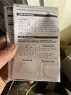
Looks familiar?
DIYnot Local
Staff member
If you need to find a tradesperson to get your job done, please try our local search below, or if you are doing it yourself you can find suppliers local to you.
Select the supplier or trade you require, enter your location to begin your search.
Please select a service and enter a location to continue...
Are you a trade or supplier? You can create your listing free at DIYnot Local
Similar threads
- Replies
- 23
- Views
- 14K
- Replies
- 3
- Views
- 1K