
- Joined
- 4 Jan 2016
- Messages
- 2
- Reaction score
- 0
- Country

Hi
Hope someone can help me...though please be patient with me & any advice in layman's terms please, otherwise I won' have a clue, which is less than what I seem to have now!
I have provided as many pics as possible to help explain my issue
Basically the problem I have is with the thermostat (Danfoss ATC) that is situated 2/3 of the way down my immersion tank, the wires that WHERE attached into this are now no longer IN IT!.

Unknowingly the cable happened to be under one of the back legs of my airing cabinet, which in front of my immersion. Anyway when this was pulled away and out off the airing cupboard, the wires became disconnected.
I have no idea how to reattach them.
I made safe the electric and removed the cover from thermostat, only it may as well be in Japanese.....I then figured if I removed the cover of the box (two port zone valve system) I may be able to get more of an idea, as well as searching on line, ending up trying to figure out all the electrical jargon regarding all the symbols, codes etc. .....anyway I'm stuck & going round the bend even more than usual!
Please could some one help me.I just need to know where to attach the wires back to the inside of the thermostat please.
-------------
So I have a bare wire (which has come disconnected from the thermostat), this is a 4 core cable consisting of these coloured wires:
- Green/yellow
- Brown
- Black
- Grey
(inside the thermostat there are 4 points to attach wires. Obliviously the earth is clearly marked. So it's just the other 3 (brown, black and grey).
The 3 remaining connection points in the thermostat are marked as follows:
1 (COM)
2 (N.C)
3 (N.O)
I know N.C & N.O mean closed & open & COM (I think) means programming, but that's about it!

The other end is connected to a TWO PORT ZONE VALVE SYSTEM:
Just to be clear of where the wires are on this system going by the diagram inside the system box:
- Green/yellow - I know this goes into the earth (I'd look very dim if I didn't at least know this one)
- Brown connected to number 9 marked as HTG.ON (Programmer)
- Black connected to number 6 marked as HTG & H.W./Orange (2-Port Valves)
- Grey connected to number 15 marked as Com (Cyl Stat)
So given this where do I reattach the wire as listed above to the Danfoss ATC thermostat?


I am guessing more information maybe be needed, only rather than give a load of unnecessary rubbish about something I know little, if anything at all about. Best I just start here and wait and see what replies I get from 'those in the know' and take it from there.
Any help would be appreciated, please be gentle with me....no mean comments please. Just some HELP!!!! Please.
Many many thanks for any help in advance
NOTE:
WIRING INSIDE TWO PORT ZONE VALVE SYSTEM (this cable can be seen 2/3rds of the way up and to the far left of the picture, where there are 2 cable, on on top of the other. The cable that has become disconnected is the bottom one. (I hope from the picture you can see this have 4 wires, where as the cable above has only 3).
Again many thanks
--------------------
update and thanks to OwainDIYer
I'm guessing now I should of mentioned the following within my original question, I apologise for not doing so.
It was simply due to me not knowing much about this. Therefore, wanting to avoid making things more complicated.
The thermostat I have the problem with, I believe is the one that was added to the heating system when I had a combi boiler installed, which is wired up to the TWO PORT ZONE VALUE SYSTEM (as shown in the above message).
My actual immersion heater has an element with thermostat exactly like this one:
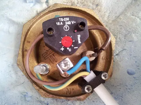
Again apologise for not mentioning this before and thanks in advance for any help.
Read more: http://www.diynot.com/diy/threads/p...tc-thermostat-immersion.450117/#ixzz3wOMqgVdT
Hope someone can help me...though please be patient with me & any advice in layman's terms please, otherwise I won' have a clue, which is less than what I seem to have now!
I have provided as many pics as possible to help explain my issue
Basically the problem I have is with the thermostat (Danfoss ATC) that is situated 2/3 of the way down my immersion tank, the wires that WHERE attached into this are now no longer IN IT!.
Unknowingly the cable happened to be under one of the back legs of my airing cabinet, which in front of my immersion. Anyway when this was pulled away and out off the airing cupboard, the wires became disconnected.
I have no idea how to reattach them.
I made safe the electric and removed the cover from thermostat, only it may as well be in Japanese.....I then figured if I removed the cover of the box (two port zone valve system) I may be able to get more of an idea, as well as searching on line, ending up trying to figure out all the electrical jargon regarding all the symbols, codes etc. .....anyway I'm stuck & going round the bend even more than usual!
Please could some one help me.I just need to know where to attach the wires back to the inside of the thermostat please.
-------------
So I have a bare wire (which has come disconnected from the thermostat), this is a 4 core cable consisting of these coloured wires:
- Green/yellow
- Brown
- Black
- Grey
(inside the thermostat there are 4 points to attach wires. Obliviously the earth is clearly marked. So it's just the other 3 (brown, black and grey).
The 3 remaining connection points in the thermostat are marked as follows:
1 (COM)
2 (N.C)
3 (N.O)
I know N.C & N.O mean closed & open & COM (I think) means programming, but that's about it!
The other end is connected to a TWO PORT ZONE VALVE SYSTEM:
Just to be clear of where the wires are on this system going by the diagram inside the system box:
- Green/yellow - I know this goes into the earth (I'd look very dim if I didn't at least know this one)
- Brown connected to number 9 marked as HTG.ON (Programmer)
- Black connected to number 6 marked as HTG & H.W./Orange (2-Port Valves)
- Grey connected to number 15 marked as Com (Cyl Stat)
So given this where do I reattach the wire as listed above to the Danfoss ATC thermostat?
I am guessing more information maybe be needed, only rather than give a load of unnecessary rubbish about something I know little, if anything at all about. Best I just start here and wait and see what replies I get from 'those in the know' and take it from there.
Any help would be appreciated, please be gentle with me....no mean comments please. Just some HELP!!!! Please.
Many many thanks for any help in advance
NOTE:
WIRING INSIDE TWO PORT ZONE VALVE SYSTEM (this cable can be seen 2/3rds of the way up and to the far left of the picture, where there are 2 cable, on on top of the other. The cable that has become disconnected is the bottom one. (I hope from the picture you can see this have 4 wires, where as the cable above has only 3).
Again many thanks
--------------------
update and thanks to OwainDIYer
I'm guessing now I should of mentioned the following within my original question, I apologise for not doing so.
It was simply due to me not knowing much about this. Therefore, wanting to avoid making things more complicated.
The thermostat I have the problem with, I believe is the one that was added to the heating system when I had a combi boiler installed, which is wired up to the TWO PORT ZONE VALUE SYSTEM (as shown in the above message).
My actual immersion heater has an element with thermostat exactly like this one:
Again apologise for not mentioning this before and thanks in advance for any help.
Read more: http://www.diynot.com/diy/threads/p...tc-thermostat-immersion.450117/#ixzz3wOMqgVdT
Last edited:


")