

Hi,
We have found that some of the radiators are coming on when only the HW is turned on. Also sometimes the pump and boiler contine to run when nothing is on.
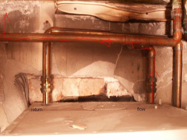
We had our old oil boiler replaced with an Ideal classic ff1200 gas boiler some time ago, but only recently realized that the rads on the top floor are on with the hot water. I lifted a floorboard on the middle floor and found that all the pipes seemed to be hot, not just the ones to the hot water tank.
There is a pump which sems to push the return into the PR connector on the boiler. Above the pump (on the other side to the boiler) is a junction and a pair of 2port zone valves.
The Boiler connection PF (I assume flow) connection comes out of the boiler, forks and both parts go up into the ceiling.
The zone valves are drayton ZA5s. My first thought was that a zone valve had failed so I bought a replacement. Looking at the replacement though it implies that the ones fitted are upside down.
The replacement has an A and B marked on the body (the existing ones are up against the wall so I cant see any direction marking) and the instructions say flow should go into the A end and out of the B end.
sort of like this where --+== represents the pipe forking into 2 and then going into the valves and the { and } represent what I think is the direction of flow (on the basis that if I turn on the heating thats the order in which pipes get hot)
[code:1]
floor. . . . . . . . . . . . . . . . . . . . . . ceiling
BOILER PR--+
|
+-----}----+
|
+---{-PUMP-{--+=={=A Zone Valves B=={==
BOILER PF--}---+===}====
[/code:1]
Its a bit more complex than that because the pipes cross over each other as they go out into the ceiling.
(Isnt it a pain trying to draw in ascii?)
The pump is a Grundfoss and I assume has a direction marking on the body but its in the corner and I cant see anything. If it helps, the text on the front of the pump is upside down (as is the text on the front of the zone valves.)
So questions for m'learned experts
A quick web search for layouts gives me that this is S-Plan. And the diagrams all seem to show that the flow should be out of the boiler, through the pump, then the valves and then off to the rads/hot water tank. Does that make sense?
What would be my best approach to sort this out?
Should the pump push water into the boiler or suck it out ?
And I assume that the valves should be on the flow side not the return side ?
As an extra thought - Could they have cross connected the hot water and CH pipes - how would I tell other than lifting carpets and floors to check where pipes go.
I hope thats given a clear picture of the problem.
Thanks for reading this far, you've earned a virtual beer token.
We have found that some of the radiators are coming on when only the HW is turned on. Also sometimes the pump and boiler contine to run when nothing is on.
We had our old oil boiler replaced with an Ideal classic ff1200 gas boiler some time ago, but only recently realized that the rads on the top floor are on with the hot water. I lifted a floorboard on the middle floor and found that all the pipes seemed to be hot, not just the ones to the hot water tank.
There is a pump which sems to push the return into the PR connector on the boiler. Above the pump (on the other side to the boiler) is a junction and a pair of 2port zone valves.
The Boiler connection PF (I assume flow) connection comes out of the boiler, forks and both parts go up into the ceiling.
The zone valves are drayton ZA5s. My first thought was that a zone valve had failed so I bought a replacement. Looking at the replacement though it implies that the ones fitted are upside down.
The replacement has an A and B marked on the body (the existing ones are up against the wall so I cant see any direction marking) and the instructions say flow should go into the A end and out of the B end.
sort of like this where --+== represents the pipe forking into 2 and then going into the valves and the { and } represent what I think is the direction of flow (on the basis that if I turn on the heating thats the order in which pipes get hot)
[code:1]
floor. . . . . . . . . . . . . . . . . . . . . . ceiling
BOILER PR--+
|
+-----}----+
|
+---{-PUMP-{--+=={=A Zone Valves B=={==
BOILER PF--}---+===}====
[/code:1]
Its a bit more complex than that because the pipes cross over each other as they go out into the ceiling.
(Isnt it a pain trying to draw in ascii?)
The pump is a Grundfoss and I assume has a direction marking on the body but its in the corner and I cant see anything. If it helps, the text on the front of the pump is upside down (as is the text on the front of the zone valves.)
So questions for m'learned experts
A quick web search for layouts gives me that this is S-Plan. And the diagrams all seem to show that the flow should be out of the boiler, through the pump, then the valves and then off to the rads/hot water tank. Does that make sense?
What would be my best approach to sort this out?
Should the pump push water into the boiler or suck it out ?
And I assume that the valves should be on the flow side not the return side ?
As an extra thought - Could they have cross connected the hot water and CH pipes - how would I tell other than lifting carpets and floors to check where pipes go.
I hope thats given a clear picture of the problem.
Thanks for reading this far, you've earned a virtual beer token.


 I haven`t even got a digital camera.