- Joined
- 3 Jan 2021
- Messages
- 5
- Reaction score
- 0
- Country

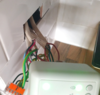
Hello,
I hope someone can help me please. I've installed Hive previously on a Vaillant Combi which was straightforward simply requiring connections at the boiler as there was no previous separate thermostat. I've just purchased my first home and I'm looking to install Hive again on a relatively new system with a conventional boiler system featuring a Worcester Greenstar 12Ri, Potterton EP2000 with a separate thermostat on from what I can understand to be a Y plan system as there's a hot water tank and mid position valve.
I've included the photos below to show the set up and wiring centre.


As far as I can interpret the wiring scheme remains the same however I do appreciate I'd also have to isolate existing themostat by either disconnecting the wiring at the wiring centre, make safe by isolating the wiring once the existing thermostat is removed or leave it set to max. I also understand that the link wire from L to 5 needs to be removed and the remaining brown wire can in 5 can then be connected to L. Am I also right in my thinking that for the all other connections I could use Wago connectors to remake all other connections not available on the Hive backplate and leave these in the wall cavity.
EP2000 to Hive
N to N
L to L
1 to 1 (HWOFF)
2 to 2 (CHOFF)
3 to 3 (HWON)
4 to 4 (CHON)
5 to L
If someone can confirm I'm heading in the right direction it would be appreciated.
Thanks
I hope someone can help me please. I've installed Hive previously on a Vaillant Combi which was straightforward simply requiring connections at the boiler as there was no previous separate thermostat. I've just purchased my first home and I'm looking to install Hive again on a relatively new system with a conventional boiler system featuring a Worcester Greenstar 12Ri, Potterton EP2000 with a separate thermostat on from what I can understand to be a Y plan system as there's a hot water tank and mid position valve.
I've included the photos below to show the set up and wiring centre.
As far as I can interpret the wiring scheme remains the same however I do appreciate I'd also have to isolate existing themostat by either disconnecting the wiring at the wiring centre, make safe by isolating the wiring once the existing thermostat is removed or leave it set to max. I also understand that the link wire from L to 5 needs to be removed and the remaining brown wire can in 5 can then be connected to L. Am I also right in my thinking that for the all other connections I could use Wago connectors to remake all other connections not available on the Hive backplate and leave these in the wall cavity.
EP2000 to Hive
N to N
L to L
1 to 1 (HWOFF)
2 to 2 (CHOFF)
3 to 3 (HWON)
4 to 4 (CHON)
5 to L
If someone can confirm I'm heading in the right direction it would be appreciated.
Thanks
")