replacing weird immersion heater timer

Joined
25 Jan 2021
Messages
9
Reaction score
0
Country
United Kingdom
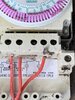
Hi everyone, stumbled across this site whilst trying to work out how to replace an old immersion timer that is different to the new one i bought, hoping someone can point me in the right direction.

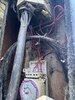
It's actually used on a lamppost rather than a heater, this is just how we found it at the property, you can see how it's wired up currently with a mains in, bridge wire, and switched live, I assume the neutrals and earths are connect elsewhere inside the lamp.

The new timer I bought simply has a load in and supply out so I'm stuck what to do, assume the mains and switched go in the load and supply so its the bridge wire i guess as I don't know what that does or where it goes, if i could get a timer switch like the one I'm taking out that will solve the issue but unsure where to get one as I think most will be simply load and supply connections.

Thanks in advance.
 

Attachments

  • IMG_8909.jpg
    IMG_8909.jpg
    316 KB · Views: 292
Sponsored Links
I think you have a supply cable, probably with a red and a black (or a brown and a blue) core, plus earth; and a load cable (to the lamp) with something similar. Is that right?

Show us the cables you have, and also the terminals on your new timeswitch.

Beware of assuming that the colour of the cores accurately represents what they do. For example the motor in your old timeswitch would not work if it had no Neutral connection, but all the cores are red.

Brush off the dust with a clean dry paintbrush, and use a permanent marking pen to identify each of the wires before you disconnect any of them. Have you got a multimeter? if not, buy one.
 
The new timer almost certainly switches both Live and Neutral while the old timer only switches what ever is linked to Terminal 3

At present Live is connected to Terminal 3 to be switched.

At present the Neutral to the lamp ( the load ) is connected elsewhere and is not switched by the timer. Hence the new timer only need to switch the Live. The Live is connected to the switch inside the new timer.


As JohnD mentioned label the wires before removing the old timer.

This should work, Ensure the power is OFF before moving any wires

xx new timer.jpg
 
this is the whole thing, the new timer is just as Bernard has sketched, that grey wire I've highlighted in blue is what goes up to the lamp holder at the top and yes will take the neutral up there too, no idea what's going on at the bottom though, they have obviously just used red wires for everything!

Bernard are you saying the bridge label means nothing in this set up and is simply either the N or L, probably the N which if the switch was carrying the N as well would bridge it to no 3 and that could take it to the lamp holder, but instead its taken up elsewhere (grey cable)?

Yes I have a multimeter so if i connect 1 and 2 wires i should get a reading meaning they are indeed the L and N, your diagram Bernard based on the bridge being the N and 1 being live, then 4 takes the L back up somewhere inside before the grey cable takes the switched live up to the fitting.

*** After thinking though if the switch doesn't pass the N on why is no 2 the N, or does the switch need N to operate? still the bridge means nothing then? ***
 

Attachments

  • IMG_8917.jpg
    IMG_8917.jpg
    425.1 KB · Views: 190
Last edited:
Sponsored Links
No, youve misread the labelling.

1 is neutral in
2 is live in. It look like that in this timer there is an internal link to 3
4 is the output.


Show us the connections to the new timer and we can tell you how to connect.
 
No, youve misread the labelling.

1 is neutral in
2 is live in. It look like that in this timer there is an internal link to 3
4 is the output.


Show us the connections to the new timer and we can tell you how to connect.
the new timer is just how bernard has sketched his suggestion to wire it up, L and N in and same out... what would 3 and 5 be used for then, are they additional switched lives?
 
just had a quick test terminals 2, 3 and 5 are all live, terminal 4 only becomes live when the timer kicks in... 1 and 2 produce a link/reading when connected using a multi meter so i assume that confirms they are the L and N in...
 
the new timer is just how bernard has sketched his suggestion to wire it up, L and N in and same out... what would 3 and 5 be used for then, are they additional switched lives?
Please understand. terminsl 3 is permanently connected to terminal 2 inside that timer. If you measure between 1 and 3 it will always be live.
termibal 5 will become live when the timer is OFF (not needed for your application). Terminal 4 will come on when the timer is ON.
Just mark the existing wires 1 2 and 4. And fit the new timer.
 
Please post a picture of the new timer on which I can sketch what you need to do.

The wiring in the post does not look good.

Whose lamp post is this ? And from where does the power in the SWA ( Steel Wire Armoured ) come from ?.
 
Please post a picture of the new timer on which I can sketch what you need to do.

The wiring in the post does not look good.

Whose lamp post is this ? And from where does the power in the SWA ( Steel Wire Armoured ) come from ?.
this is the new switch which from what you guys have said needs to be (right to left) wires 2, 1, skip, skip, 4 from the old unit.

its a lamp in my back garden, house was a self build (not by me) so i can imagine they may have just used any old wires to fix it up, the power is from my meter and can be isolated by a fused spur in the near by garden room...
 

Attachments

  • IMG_8920.JPG
    IMG_8920.JPG
    210.2 KB · Views: 145
Links in this post may contain affiliate links for which DIYnot may be compensated.

DIYnot Local

Staff member

If you need to find a tradesperson to get your job done, please try our local search below, or if you are doing it yourself you can find suppliers local to you.

Select the supplier or trade you require, enter your location to begin your search.


Are you a trade or supplier? You can create your listing free at DIYnot Local

 
Sponsored Links
Back
Top