room stat operates even when programmer is off

Thanks for the replies.

Would the programmers red LED, that shows it is on, still be able to extinguish, when turned off, if the relay is stuck? Because it does go off, with a click? When I get home I will test if term 4 is 240v or not, I guess this would prove the stuck relay theory?
 
Sponsored Links
T 4 could be volts free.

You'll need to check whether there's a link internal and what it link from/too.
 
The only link I remember is one that selected 24v or 240v, 240v was selected, it was a dil switch on the back. Not sure how I would find out about any other type of link.

I feel I may be about to get lost, would a house be able to be built and the full heating system not be checked whether it works properly. I thought in this day and age everything had to be checked on a new build?
 
Yes everything has to be signed off as checked and working whick is why you should get the builder to sort it, no matter how many times it takes.

The Dil switches select fully pump/gravity 7day/24 hour etc
 
Sponsored Links
I know your right, I should, but its very difficult when they take 6 weeks to come out and even need my assistance when they do get here, sooo frustrating.
 
Would the programmers red LED, that shows it is on, still be able to extinguish, when turned off, if the relay is stuck? Because it does go off, with a click? When I get home I will test if term 4 is 240v or not, I guess this would prove the stuck relay theory?
The red light will still work, but if you can hear a click, it sounds like it may be working (sorry for the pun) the only real way to know is to test it. If it is working then you need to find where the thermostats are getting their permanent live supply from.

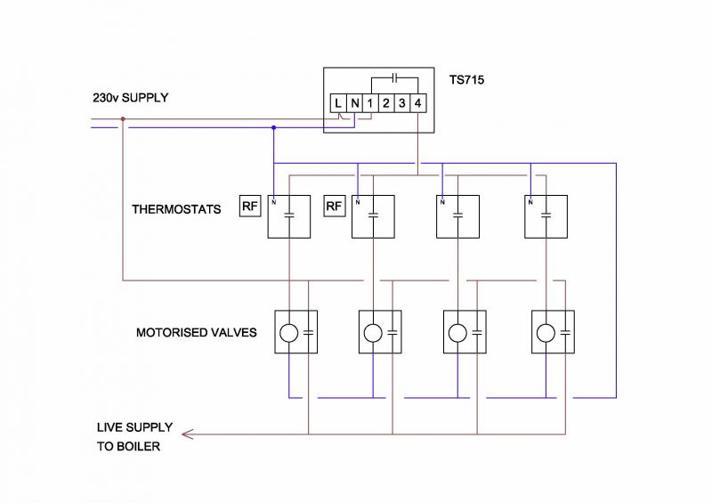
Here's a diagram showing how I would expect your system to be wired assuming you have 4 motorised valves controlling it, the UFH may have different controls, but it shows the thermostat connections to the timeswitch.

 
Ive just checked the lounge honeywell dt90 thermostat and there are only two wires connected, brown to term A with constant 240v (whether the programmer is on or off), black with brown sleeve to term B and nothing in term C.

A green and yellow earth wire to the earth tag on the cage. A grey wire with a short blue sleeve which is doing nothing in a chocolate block.

As far as I'm concerned this is the only part that had the wires changed, when the danfoss stat was changed to this honeywell one

Any clues?

Many thanks
 
Thinking about it, I reckon the plumber has miss-wired a constant live to a switched live in the main junction block and bypassed the programmer. I can't think of a way of knowing whats what in the main junction block as it has mains in, wires to the boiler, wires to a valve, wires to the wireless honeywell unit and wires to what I guess is the downstairs stats. All too much for me, I might as well pay for someone to correct his bodge, if there is someone capable of sorting this mess out. I don't really have much faith left.....shame really because it is probably only down to one wire :eek:(
 
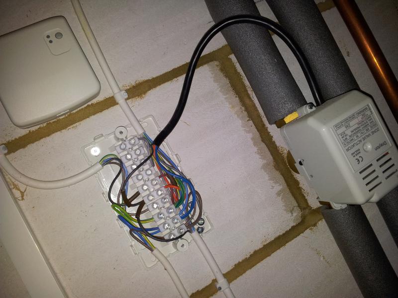
(photo on the left) Top left is to wireless honeywell upstairs stats, bottom left is mains in, bottom right is to programmer, black top right to actuator valve and white top right is to downstairs stats, i think?
 
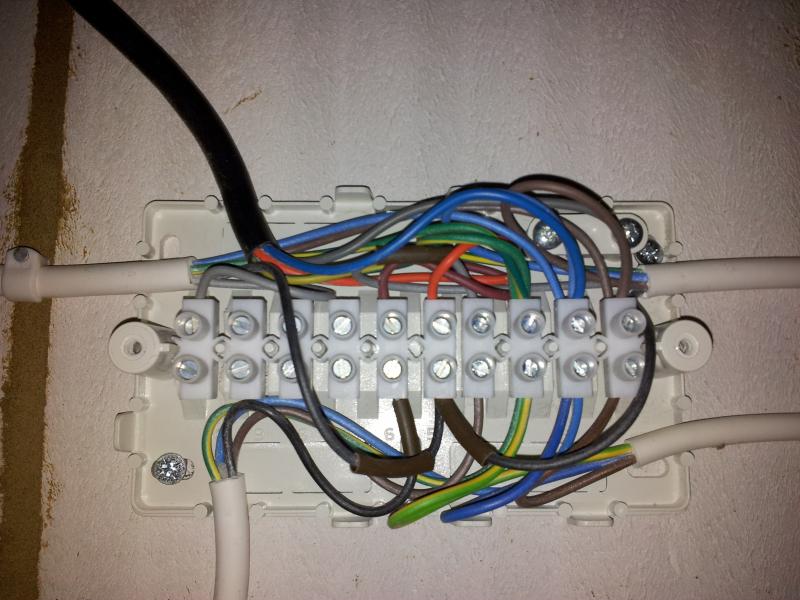
Good photo of some messy wiring, but it's not possible to trace all of the wires visually. (For example, I can only see orange and blue wires from the motorised valve). I think you may have given the bottom two cables the wrong identities. It would be more usual for the mains supply to use a three core cable so that would be the bottom right one. If that is the case then it looks to me as if the mains supply goes straight to the upstairs and downstairs thermostats which would mean that they are permanently powered. Also the programmer would need four cores (unless it picks its main supply up straight from the FCU rather than the junction box)

Even if all the wires could be seen, the photo only gives half the story and we would also need one for each of the other ends of the cables.

I am also puzzled that there is only one motorised valve, when you have four zones. If there are others, there must also be some other junction boxes elsewhere.
 
Thanks Stem,

I think there are other valves directly under the programmer which are the under floor heating valves. The programmer and the under floor heating manifold is the other side of the wall of the photo and about two foot lower so maybe thats where the bottom cables head off to. I'll see if I can separate the cables for better viewing.

Many thanks
 

DIYnot Local

Staff member

If you need to find a tradesperson to get your job done, please try our local search below, or if you are doing it yourself you can find suppliers local to you.

Select the supplier or trade you require, enter your location to begin your search.


Are you a trade or supplier? You can create your listing free at DIYnot Local

 
Sponsored Links
Back
Top