Three Port Valve Query

Joined
28 Jan 2011
Messages
5
Reaction score
0
Location
Berkshire
Country
United Kingdom
Hi,

I have a strange problem with a new install of a 3 port valve which I could not find on this site.

I have installed a Hortsmann F322m 3 port valve and I have noticed that with CH only, everything is fine: The CH light comes on and pipes to heating side warm up.

With Hot water only (after turning up the cylinder stat) the HW light comes on and the pipes on the HW side only warm up which is correct.

If I select both and HW temperature satisfied, only the CH light comes on. If I turn up the Cylinder stat (to call for HW) both lights go off. In this state, I noted that the grey wire only had 240 v which sounds wrong and I wondered if anyone new what the problem could be?

I have tested the following states with a Voltmeter (measured with respect to neutral):

HW only (calling) - Looks correct
Grey 0v
Orange 230v
Blue 0v
White 0v

CH only calling
White 240 v (looks correct)
orange 68 v (possibly correct)
Grey 48 v (seems low, possibly induced?)
Blue 0v

CH and HW (HW calling) Looks very wrong:
White 0v
Grey 240 v
Blue 0v

From this it appears that Blue and Orange are in the correct position. The last state implies that grey and white are the wrong way round but this would contradict the CH only state (as White is correctly receiving 240 v).

Is it possible that the valve has been wired correctly but the cylinder stat wiring is wrong.

Many thanks.
 
Sponsored Links
HW only (calling) - Looks correct
Grey 0v
Orange 230v
Blue 0v
White 0v
That's correct, but the 230V on the orange is not coming from the valve but from the call terminal of the cylinder thermostat, which is connected to the same terminal

CH only calling
White 240 v (looks correct)
orange 68 v (possibly correct)
Grey 48 v (seems low, possibly induced?)
Blue 0v
Grey and Orange should both be 240V

CH and HW (HW calling) Looks very wrong:
White 0v
Grey 240 v
Blue 0v
White should be 240V
Grey should be 0V

Possibly white and grey have been reversed

From this it appears that Blue and Orange are in the correct position. The last state implies that grey and white are the wrong way round but this would contradict the CH only state (as White is correctly receiving 240 v).

Is it possible that the valve has been wired correctly but the cylinder stat wiring is wrong.
That's possible. Is the valve the correct way round - Port A to heating, Port B to cylinder?

Here is the correct wiring for a mid position valve. The cylinder stat terminals are:

C - common
1 - On/Call
2- Off/Sat

View media item 31288You may also find How a mid-position valve works helpful.
 
Thanks for the reply. The wiring diagram is useful. In answer to your question, I have checked the valve is the right way round: HW goes into the cylindler and CH goes to the central heating.

I thought the readings were strange, thanks for confirming that. I did try reversing grey and white but in that state for CH only I obtained the following readings:

CH only calling
------------------
White 48 v (should be 240v)
Grey 240 v (correct)
Orange 68 v (suspicious, although measured with respect to neutral on valve not the cylinder stat)

HW only on at programmer (not calling)
White 240 v (implying grey was the right way round initially)
Orange 240 V
Grey 0v

I guess either the cylinder stat has been wired wrongly (unchanged) or I have been unlucky and bought a faulty motorized valve (which should be easy to replace as the head comes off luckily).

I think I shall have to look at the entire wiring centre in accordance with the schematic you sent as the readings are contradictory. I'll let people know what the problem is when I find it as it is quite obscure.

Thanks for the help!
 
Sponsored Links
Hi,

sorry for the delayed reply to this post, I have been very busy of late. Anyway on to the valve, I think I have solved the problem (thanks for the assistance):

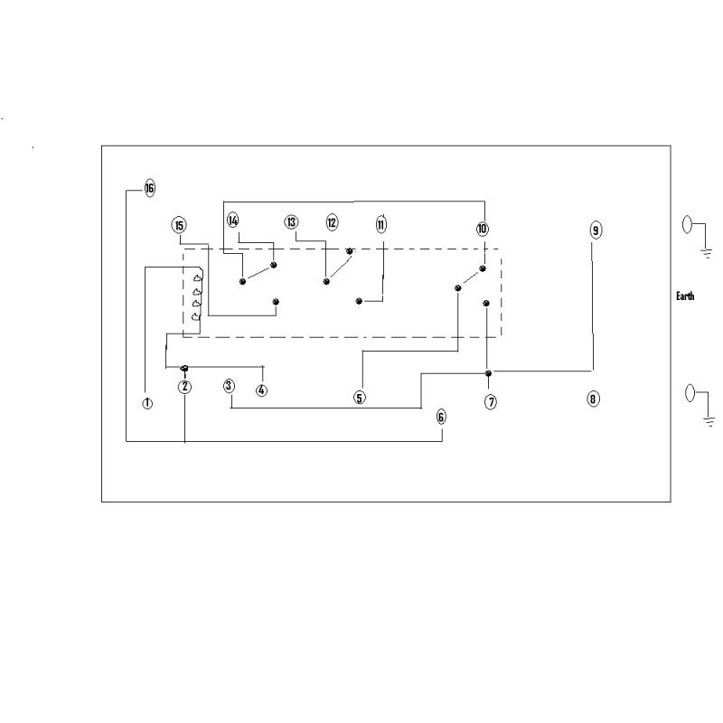
The original valve that I replaced was a mid position valve, but having analysed the circuit (please see diagram) this is not a Y plan and so it should have been a diverter valve. I have found that by detaching the orange wire (and covering the end) the boiler and pump still come on when calling for Central heating only; I think this in itself proves it is not a Y-plan system - the pump and boiler should be energised by the orange lead in CH only position (but fed in the HW only position) and the grey lead should be on. Since I also (wrongly) replaced the Mid position valve with another I have effectively made it behave as a diverter by joining the white and grey lead and removing the orange lead from the circuit. This works perfectly as a Hot water priority system which, being in a flat, is fine from a practical point of view.

As you can see from the diagram, there is a relay in the circuit (which apparently is quite an old design)


Using a voltmeter I have determined that 10 is HW on; 11 is HW off.
9 is the feed to the switch.

A continuity test confirmed that the Switch had been wired correctly

16 = 2 = 6 (Neutral)

1 is from the programmer and energises the relay.

Now if Hot water is called for and CH is off (not called for) 10 energises 14
If HW is called for and CH is on the relay is energised and the switch moves from 14 to 15 so 10 energises 15.

If Hot water is satisfied 10 will have a small induced voltage, but 11 will be energised. This will energise 13 if and only if the switch has moved down which will only happen if the relay is on when CH is called for. Otherwise 11 will be disconnected.

I have therefore attached white and grey to 13 and removed the orange lead (which was originally on 14). This works correctly and the boiler and pump still come on when CH only is called for.

For completeness I also tested the behaviour of the 3 port valve using the tests you sent me (thank you - these proved the 3 port valve worked correctly - a pity I did not buy a diverter, though!)

Please note, there are also other terminals 17, 18, 19 and 20 which Satchwell did not display on the internal wiring diagram, but using the voltmeter I have confirmed that these correspond to the Programmer.

Thank you very much for your help. I can now control HW and CH independently as a HW priority system (W - plan I think)


Many Thanks.
 
The giveaway would have been how many wires your old valve had if three, its W Plan. If five, its a Y Plan.

Anyhow, it would be better to persevre and change to a Y Plan, mid-position valve. Only a few wiring changes needed, and it means that you don't lose the heating when the cylinder is heating up.
 
Hi,

Thanks for the reply. The original valve did actually have 5 wires which led to the confusion. The previous installer must have attempted to put in a Mid-position valve when it should have been a diverter (which as you say has 3 leads). For example, with the old valve CH was wired to 15 which becomes disconnected when CH is called for (clearly wrong). So it was not obvious (if you assume the previous installation was right), hence the detailed analysis :) .

Thanks.
 
The acid test though, is if your rads went cool when the hw was on. If yes, then it was wired as W Plan.
 
True! In hind sight this would have been easier than painstakingly working out what each terminal corresponds to (although it did mean I could work out that the white and grey needed to be attached to 13). Am I right in saying that having a relay box is quite an old design. Presumably, if I wanted to have a Y plan (being a small property it is not really necessary) it would be better to start from scratch as in the wiring diagram a previous member sent, there was no relay in the circuit. A project for another time, perhaps.

Thanks
 
If its a small property, you might be happy with what you have.

Yes, it would be best to start the wiring centre connections from scratch rather than trying to rehash things.

If you sat down with the Sundial Y Plan wiring diagram, and took your time, it wouldn't be difficult.

We are here with advice.
 

DIYnot Local

Staff member

If you need to find a tradesperson to get your job done, please try our local search below, or if you are doing it yourself you can find suppliers local to you.

Select the supplier or trade you require, enter your location to begin your search.


Are you a trade or supplier? You can create your listing free at DIYnot Local

 
Sponsored Links
Back
Top