Timed extractor wiring

Joined
7 Mar 2014
Messages
12
Reaction score
0
Location
Lincolnshire
Country
United Kingdom
Hi all, I'm a total newbie and struggling.
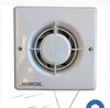
My old kitchen fan broke so decided to buy a new one. The old one was a man rose pull cord that had it's own switch (it connected straight to it's own fcu switch which one turned on you just pull the cord) I've disconnected the fan and noticed it just has L&N from fcu.
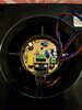
My new fan is a knightsbridge timer fan with NO pull cord. I cant I fit this to the original wiring as it says it needs extra wires. I do not want the fan to be connected to the lights, but all instructions I can find is for it to be connected through a light switch, I just want it connected like the old one was.
Can this even be done, any advice would be appreciated but please dumb it down a bit (nothing too technical) lol
 
Sponsored Links
pull cord that had it's own switch (it connected straight to it's own fcu switch which one turned on you just pull the cord)
I am reading there is a switched FCU and a pull cord and you want to use just the switched FCU? I can't see the problem? If not a switched FCU then change it to a switched FCU.

What is the problem?
 
My old fan was a bigger version of the one in the photo, it only connected to the fcu by two wires. (You turn the fcu switch on then pulled the fans pullcord).
My new timer fan only has instructions for it to fitted through the lights (like a bathroom fan), I do not want this. I wanted to know how to wire it through my original wires (if it can) i dont necessarily need the timer to work just as long as I can turn it on and off through the fcu switch.
 

Attachments

  • 20210310_223843.jpg
    20210310_223843.jpg
    248.1 KB · Views: 90
you link "L" and "SL" together in the fan.

I think you've got a little WC fan which is inadequate for a kitchen.
 
Sponsored Links
Look inside the fan at the connector block. Compare it to your instructions and tell me what it calls the terminals. You can post a pic if you want. Copy and Paste it into your reply.
 
is that the new one? It seems to have rather a lot of red and blue wires on the right. I wonder what for? Electric shutters? Switch? Humidity sensor? neon indicator?

At the bottom of the pic I can see a cable clamp, which I will guess is for your incoming cable, and three terminals marked T, L and N

I will guess that N is Neutral and L is Live and T might be Timed. If this is so, you would bridge L and T together, and the fan will run all the time that you supply power to L and N.

You will have to read your instructions to see if my guesses are correct.

such fans more often have terminals marked SL, L and N, where SL is switched live.
 
Hi john, the wires are because a led light is fitted to the fan.
To loop the L to T do I just use a 1.5mm piece of copper wire connect to L with the original wire then connect it to T?
 
Hi john, the wires are because a led light is fitted to the fan.
To loop the L to T do I just use a 1.5mm piece of copper wire connect to L with the original wire then connect it to T?


It must be insulated. If your incoming live wire is red, use red.

If brown, use brown.
 
The two wires from the fcu are red and black.
How do I insulate the wire, is it just a case of putting a sleeve over it?
 
That's what I'm asking, for it to insulated does that just mean it is sleeved.
Like I said I'm a newbie
 

DIYnot Local

Staff member

If you need to find a tradesperson to get your job done, please try our local search below, or if you are doing it yourself you can find suppliers local to you.

Select the supplier or trade you require, enter your location to begin your search.


Are you a trade or supplier? You can create your listing free at DIYnot Local

 
Sponsored Links
Back
Top