
Two Way Lighting - Which way to do it?

Joined
25 Nov 2025
Messages
45
Reaction score
4
Country
United Kingdom
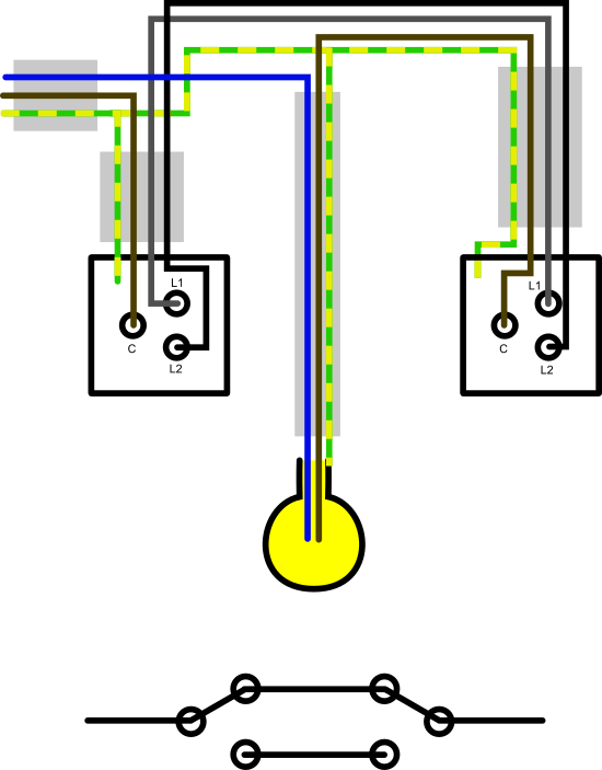
Hopefully a nice and easy one for all you pros, but this is my first time wiring up a two way light circuit. I have a friend that's a retired electrician (still does the odd bit of work on the side) and he's given me some advice, but before I sought his help I came up with this:
two_way_lighting_1.png


This makes a lot of sense to me and looking in the wiki, this (below) is front and centre; exactly what I was thinking of above.
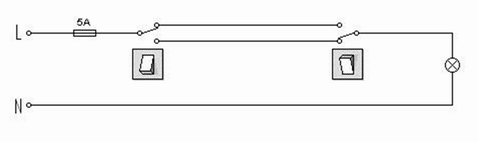
1788636888597.png


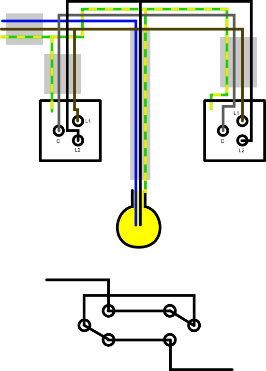
Now, my electrician friend drew out a diagram with me and suggested this:

two_way_lighting_2.png

Again, on the wiki, just below the design I came up with is this (below). It looks the same as my above diagram and what my electrician friend presented to me.
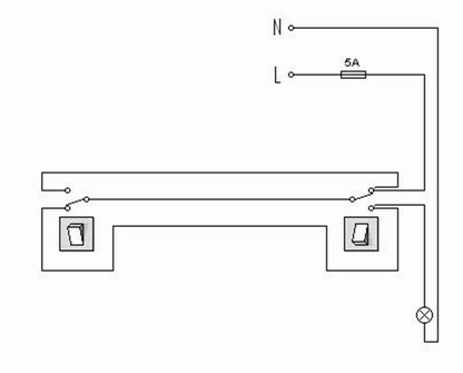
1788636927004.png

I'm glad I found both on the wiki, gives me confidence that I won't go too far wrong, but it left me with questions. Obviously this is second nature to my electrician friend, but despite me explaining how I was going to approach it, he directed me towards the second version. The first version makes a lot of logical sense to me, the second version, while I can follow it, feels far less straight forward, so my main question is why I would choose one over the other?

Obviously if I've asked for advice from someone and I'm arguing the toss or asking "why" too many times isn't a great look, so I just wanted to talk it through without the social implications.

Thanks in advance!

P.S. I might have the wire colours wrong in my diagrams above, sorry about that, happy to be corrected on those, but I'm mostly interested in the wiring logic.
 
Just wire it as you normally would a one way then put a 3 core and earth between the two switches.

Screenshot_20260905_215555_Chrome.jpg
 
Thanks Pete. That looks to be the same way that my electrician friend was suggesting. When both options are in the wiki (and therefore, I assume viable), my question is why choose one over the other?
 
The first way seems a bit more awkward to me, I think it was done more years ago when they used to use sheathed single cables.

I've never done it in a house, only when wiring in conduit.
 
Yeah, perhaps that's it. The way I thought of approaching it seems simpler logically, but the way you and my electrician friend are suggesting sounds like it could be practically simpler. "put a 3 core and earth between the two switches" does take a lot of thought out of it.

Thanks
 
This is the rough layout (cross section of the elevation). House on the left, newly built porch on the right. Supply is the red line, lights are yellow and switches grey.
1788644175484.png

It will be two two way switches (and I might be including a Zigbee smart relay for the outside light), but I'm happy to focus on a single light, without the smart relay (as I don't think that adds much complexity or changes much).

Thanks
 
So the obvious way to route the wires is everything meeting at the left light, correct?
 
Yeah, that's what I was thinking. Some junction box in the porch ceiling to pull it all together.
 
But if, say, the switch in the porch was substantially further away, then it would make more sense to go with Pete's suggestion, as it would save on cabling? I assume that's the main difference in the two approaches, how much cable you use depending on the position of the switches?

Also, is one more common than the other, so if a pro came in and took a look at some point, would doing it the way I initially proposed be unusual?
 
But if, say, the switch in the porch was substantially further away, then it would make more sense to go with Pete's suggestion, as it would save on cabling?

No, I don’t think that changes anything.

But consider the case where the easy way to route cables is supply-switch-switch-light-light. In that case, your first method requires only T&E and 3&E, but the second method requires 4 cores between the switches.

Also, is one more common than the other, so if a pro came in and took a look at some point, would doing it the way I initially proposed be unusual?

Not unusual, no.
 
I'll take your word for it in your example, but I understand the gist of what you're saying. Sounds like it's a case-by-case thing that I should draw out before doing, so I'll have either an easier time of running the cables or potentially less cables to run in total.

Thanks for the explainer, like you say. In this instance, I diagrammed both out (my original post) and it looked similar enough. Not sure why my electrician friend was guiding me towards the second method, perhaps that just what he's used to...
 
The "easier way" to do it and think about it was of the two switches the Com (Common) terminal of each switch was one of them to the L incomming supply and the other one was to the lamp say in singles,
then L1 of one switch to L1 of the other switch
and also L2 of one switch to L2 of the other switch.
(It does not actually matter if you get one of the L1 & L2 terminals the other way around, it will still work).
Again originally done in singles (and in conduit at the time).

Later on the singles became sheathed and there was also Single and Earth cables and Twin and Earth cables but the same methods of connections to terminals remained the same.

Then (possibly when some were converting an existing one way lighting circuit into a two way lighting circuit) it became "easier" to merely add a 3 core & E from the existing switch to the additional switch position.

So whether you do the first way or the second way is purely a matter of choice.
You might or might not also be influenced the the cost and labour used in one way or the other way but not usually a factor.

Personally (with Loop In from ceiling rose method) I`ve always found it faster and easier to go for - Rose to switch one in T & E then switch 1 to switch 2 in 3C & E.
But it does not really matter.

One benefit of the 3 core (& E) cable between the two switches method is if anyone has an Induction loop hearing aid it used to be a lot less chance of imparing usage of that hearing aid - a similar effect might happen to some oversensitive electronics circuits.
Because you are making the electricity flowing less around a big loop in a room into more of a flat there and back sort of shape.
Possibly, modern hearing aids suffer less from that feature nowadays?


I did come across one case where someone had missunderstood their electrician friends advice and did not use twin and earth on either switch on a two way switch circuit but instead run a 3C & E from the rose to switch 1 and also a 3C & E from rose to switch 2.
My intial gut reaction was to think "No that`s wrong!" yet I soon realised no it was not wrong and could indeed it would work that way but you would need an extra choc block/crimp/wago in the rose and slight alterations to the rose connections yet only one 3 core to each switch and no T & E to either .
So if anybody actually does that way should we nominate that as say " 2nd option version B" and classify the one you`ve already mentioned as version A ? ;)
 
The first way seems a bit more awkward to me, I think it was done more years ago when they used to use sheathed single cables.

I've never done it in a house, only when wiring in conduit.

I think it used to be a common way of wiring the 2-way switching of the landing light.
 

If you need to find a tradesperson to get your job done, please try our local search below, or if you are doing it yourself you can find suppliers local to you.

Select the supplier or trade you require, enter your location to begin your search.


Are you a trade or supplier? You can create your listing free at DIYnot Local

 
Back
Top