Underfloor heating pipes laid - now I'm getting jittery!

Joined
6 Oct 2013
Messages
5
Reaction score
0
Location
South Glamorgan
Country
United Kingdom
So I laid all the pipes and now it's time to put in the controls and whotnot. Have fixed manifold and pump to board as (briefly) explained and advised by the heating engineer at my workplace (control unit at top of board so not shown in pic). Still have niggling doubts about this as I don't fully understand how it works and I have seen all manner of configurations when googling.

Pictures of progress so far in link below - could anyone confirm this is OK before I start tightening and soldering up? Was thinking about making small tapped hole in upper manifold and securing temperature probe (in red foam sleeve). Need advice on this too.

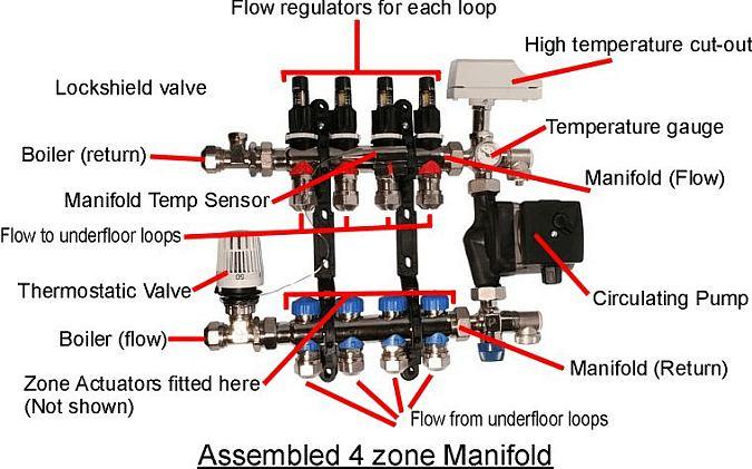
I would be extremely grateful if anyone could tell me what the bits are that I've ID'd with a question mark and how they work together.

pic here www.pepler.com/ufh.jpg

Thanks in advance!
 
Sponsored Links
No, unfortunately no pictures, instructions or manual - it came as a "gift". Have had to be a little inventive esp. with the mounting brackets!
 
Sponsored Links
That's an injection system.
With an over heat protection stat fitted in order to interlock the ufh pump.
 
Seems odd to get a gift of UFH parts without any instructions!

Have you thought of contacting the donor?

Or taking the heating engineer home from work?

Tony
 
Flow regulator manifold on the top according to the image.

Its likely in the ops set up they won't register the correct flow!
 
Flow regulator manifold on the top according to the image.

Its likely in the ops set up they won't register the correct flow!

I know what you mean, I've got the Unipipe picture printed out and have already spent some time scratching the old noggin. When I showed it to engineer he said either the pic must be wrong or I have a different type of flowmeter.

I have them in front of me now and it's clear they can only work on the return manifold. They function whereby a rod protrudes right through the manifold as far as the point where the water enters the manifold. On the rod is a small disc which is pushed upward by the incoming water thereby moving the indicator in the transparent tubey bit on top.

I suppose my main question now is - given that the flowmeters must be located on the return, is there any problem with the location of the actuators? (only two shown in my pic - I do have two more). Also, should the probe be on the flow manifold or the return?

Thanks everyone for all the contributions btw!
 
Have you pushed on the disc to see what direction it moves?
Does the numbering start top or bottom?


As you can see from the image below this flow meter needs to be on the flow manifold........
4a35.jpg


The sensor is fitted on the flow manifold as close as possible to the inlet side.
 

DIYnot Local

Staff member

If you need to find a tradesperson to get your job done, please try our local search below, or if you are doing it yourself you can find suppliers local to you.

Select the supplier or trade you require, enter your location to begin your search.


Are you a trade or supplier? You can create your listing free at DIYnot Local

 
Sponsored Links
Back
Top