Wiring a Salus UFH wiring centre RF

Joined
5 Nov 2018
Messages
21
Reaction score
3
Country
United Kingdom
Hi all. I hope you are well.

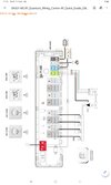
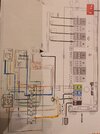
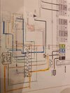
I have just installed a underfloor heating manifold with the above controls.mplease see image attached. This is attached to a combi where I have installed 2 zone valves so basically an S plan. Now looking at the wiring centre schematic, it does not go from the usual switch live on the brown to orange and to the boiler. I cannot quite get me head around the wiring set up. So do I join the pump to the grey, neutral and green on the zone valve and then grey to pump on fr centre. Then run a cable from boiler in front centre to stat locations in the boiler and not use the switch live of the zone valve.

Thanks all.
 

Attachments

  • Screenshot_20220921-125046_Drive.jpg
    Screenshot_20220921-125046_Drive.jpg
    120.2 KB · Views: 162
Sponsored Links
Ahh gutted. Thought I would get one reply. Stem usually answers my questions but no such luck. Could anyone point me in the correct direction? I was typed into Google the issue I have and a thread came up on this site with someone who was asking the same questions as me. I accidentally closed the browser and could not find it again. Been going back through the posts for hours but no luck. Stem, the old Faithfull with these wiring issues was there. Think it was 2019. Any help?

Thank you
 
You shouldn't need a zone valve with this, but now you have one you may as well use the switch live out from the boiler connection to switch the brown on the zone valve. The UFH manifold pump goes to the pump connections as you've correctly identified.
 
Thanks for the reply. Appreciate the advice. So I can take the pump supply from ufh manifold to the LNE in my wiring centre, send a live from the pump in my wiring centre to the ufh wiring centre and then use the a supply from boiler 2 in ufh wiring centre to switch live on valve (brown wire) in my wiring centre. Is it also ok to take power from the wiring centre to power on the ufh wiring centre? Cannot see any where where it mentions this.

Thank you
 
Sponsored Links
You shouldn't need a zone valve with this, but now you have one you may as well use the switch live out from the boiler connection to switch the brown on the zone valve. The UFH manifold pump goes to the pump connections as you've correctly identified.
Just got around to thinking about this. Not sure if you can understand my sketch or not as it is a bit like spaghetti junction. Like a lot of heating system wiring done in a single back box.
 

Attachments

  • 20221005_195658.jpg
    20221005_195658.jpg
    272 KB · Views: 53
Your zone valve only seems to have 4 wires, should be 5. Brown core is connected to the wiring centre's boiler SL terminal, orange goes to the boiler
 
Doh! Missed the orange from the valve.

That make sense?
 

Attachments

  • 20221005_203102.jpg
    20221005_203102.jpg
    255.9 KB · Views: 67
Hey, I see most of the other ufh wiring centres are able to take a second zone valve bit I am thinking this one doesn't? Do you think the links that are shower from power to pump 2 and boiler 1 are already there?

Think I must be over thinking this...
 
Totally understand. Thanks for your patience Muggles. Think I can actually take the brown from the valve with the live to the pump to pump connection as in the picture and then switch live from boiler 1 connection to switch live in wiring centre. No need for grey and orange wires from the valve.
 

DIYnot Local

Staff member

If you need to find a tradesperson to get your job done, please try our local search below, or if you are doing it yourself you can find suppliers local to you.

Select the supplier or trade you require, enter your location to begin your search.


Are you a trade or supplier? You can create your listing free at DIYnot Local

 
Sponsored Links
Back
Top