Hi,
I have a central heating/hot water system which is misbehaving. It has the following components:
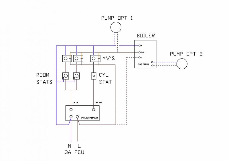
1 potterton boiler
1 potterton timer switch with controls for hot water and for CH
3 Honeywell zone valves controllong HW, half the house's CH, the other half's CH
1 HW cylynder thermostat and 2 room thermostats (1 for each half of the house).
Pump
Does anyone know where I can find a wiring diagram for a system like this?
In hope,
Paolo.
I have a central heating/hot water system which is misbehaving. It has the following components:
1 potterton boiler
1 potterton timer switch with controls for hot water and for CH
3 Honeywell zone valves controllong HW, half the house's CH, the other half's CH
1 HW cylynder thermostat and 2 room thermostats (1 for each half of the house).
Pump
Does anyone know where I can find a wiring diagram for a system like this?
In hope,
Paolo.