Working out thermostat wiring

Joined
11 Oct 2022
Messages
8
Reaction score
1
Country
United Kingdom
Hi

I have moved to a new house. One of the thermostats is broken. It's an s plan system with two zones.

Both thermostats are wired differently (!). I cannot work out the wiring. I expect one to be neutral, one to be live in and one to be switched live out. But they go to different points and I don't know what the 4th wire is for??

Photos are attached.

Can anyone please help me understand:

- how the wiring works? It does not seem to match the wiring diagram...
- what wires I would use for a new digital stat that requires power (programmable).

Thank you in advance
Phil
 

Attachments

  • 20230107_091549.jpg
    20230107_091549.jpg
    176.8 KB · Views: 169
  • 20230107_104747.jpg
    20230107_104747.jpg
    176.9 KB · Views: 159
  • 20230107_114146.jpg
    20230107_114146.jpg
    289.5 KB · Views: 152
Last edited:
On investigation the broken thermostat controls a valve which comes after the first CH valve...i.e. the first one (covering all heating) has to be on for the second (covering top floor) to receive hot water.

I don't understand any of it but it may help someone understand the wiring?

Thanks
Phil
 
On investigation the broken thermostat controls a valve which comes after the first CH valve...i.e. the first one (covering all heating) has to be on for the second (covering top floor) to receive hot water.

I don't understand any of it but it may help someone understand the wiring?

Thanks
Phil
That doesnt make any sense, post pics of all valves and controllers of any type
 
Thanks. I appreciate it doesn't make sense.

More photos attached showing HW and CH valves off pump, the extra valve, the wire connection for the extra valve (it doesn't use the orange), the mess of the wiring centre, and the potterton controller.

The heating does work to all radiators / both zones, except the broken thermostat doesnt do anything.

Could it be the second CH valve stays open until he the temp is reached at which point it switches the valve shut? (I am struggling to understand the wiring at all, and I haven't therefore changed the thermostat yet).

Thanks.
Phil
 

Attachments

  • 20230108_155714.jpg
    20230108_155714.jpg
    200.6 KB · Views: 81
  • 20230108_154505.jpg
    20230108_154505.jpg
    267.1 KB · Views: 79
  • 20230108_154426.jpg
    20230108_154426.jpg
    274.8 KB · Views: 82
  • 20230108_153423.jpg
    20230108_153423.jpg
    379.8 KB · Views: 83
  • 20221224_085441.jpg
    20221224_085441.jpg
    378.4 KB · Views: 84
Is anyone able to help with explaining the existing thermostat wiring?

Thank you
 
I’ll try and find a diagram if I can
 
Last edited:
Can you confirm the make and model of each thermostat, I suspect they are Robus RRF10's. Based on your first post, does one zone thermostat work and the other not? Can you also post pictures of the wiring for both thermostats and indicate which works or not.

If they are Robus RRF10, you only need connections to terminals 2 & 3 for heating. The secondary connections support the optional neon indicator.
 
Yes, both Robus rrf10. Wiring is shown in the pictures above.

The thermostat that works - i.e. pump and boiler off when turning down - (the one not broken in the pictures above) doesn't have wiring to 2...

The thermostat that is physically broken (shown in pictures above) does have wiring to 2. The heating to this zone does work and I don't know if the thermostat would do anything if it wasn't physically broken.

Any recommendations welcome. I am nervous about installing digital stats (Heatmiser Edge) until I understand the existing wiring.

I haven't come across an s plan with a zone within a zone before! Add the odd thermostat wiring to that and my DIY confidence is falling away..
 
I’ll send a message later but I’d personally install a hive stat
 
Just to check which is broken as you have a few pics … can you reply with the pic of the broken stat wiring thanks
 
OK. Just to ensure we know which is which

Thermostat A (picture 20230107_091549) which is physically ok
Thermostat B (picture 20230107_104747) which is physically broken

Ensure boiler power is turned off prior to making any changes, you don't want to receive a nasty shock.

From what I can see looking at the installation guide the RRF10 only needs connections on 2 & 3 for heating.

Can you also confirm that each of the connections on both thermostats are independent cores (i.e. there are no links between terminals). Do you have any terminal blocks to allow some checks to be done?

If we assume Thermostat B was turned up sufficiently prior to being physically broken I would expect the heating to come on for this zone as the wiring looks ok (#2 & #3 have connections). From what you said in your post today that does seem the case. I'm ignoring neon terminals for the moment as that is a nice to see indicator.

I would also assume Thermostat A does nothing when the dial is turned. If so move the blue in #4 over to #2 to match the connections on the phsycially broken thermostat.

The neon side of each thermostat looks incorrect as well. According to the installation guide there should be a neutral into #6 and then #4 & #5 linked. For the moment i would recommend you disconnect the blue & brown cores going into 1/5/6 and safely isolate into separate terminals on a block. That would leave the neon indicators off initially. Once the switching side is working, the neon's can be addressed.
 
Last edited:
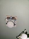
In the main thermostats control the motorised valves, then the motorised valve controls the boiler, and it seems the main fault is the micro switch in the motorised valve fails.

With better systems the motorised valves are controlled with the on/off contacts in the thermostats, and the thermostats are set to master and slave and the master one connects to boiler turning it up and down rather than on/off, but although firms like EPH make these thermostats, they are not very common, you clearly don't have them fitted.

What many do is get rid of the hard wired motorised valves, and use TRV's instead, the electronic TRV is a motorised valve, and can connect to a hub or a thermostat or control boiler with the temperature of the return water.

Hive, Evohome, Wiser, Tado all have a system where the TRV's tell the wall thermostat to turn on/off. The twin motorised valve was a knee jerk reaction by the trade to satisfy government rules about being able to control zones within the home, electronic TRV heads also form zones, and more successfully that simply upper and lower floors.

Step one is work out what you have
1673348401172.png

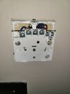
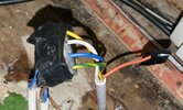
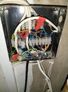
Putting a number on every terminal helps, it seems likely 12 is to boiler, as orange cables which is likely from the micro switch in the motorised valve, but seems odd to be connected to blue wires.

16 looks like an earth, but 1 and 8 have green-yellow cables which should be earth, but also brown, which is normally line.

The regulations say "The bi-colour combination green-and-yellow shall be used exclusively for identification of a protective conductor and this combination shall not be used for any, other purpose." but it seems plumbers can't read, as found loads of green-and-yellow wires used by plumbers as lives.

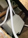
That junction box looks like a nightmare, my house was the same, there is no quick fix, but in the main motorised valves come with the cables, so the colours from the motorised valves are normally correct, so you can start with that cable.

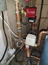
I worked out where each of my cables went, labelled them, then disconnected the lot and started again, but I did it in the summer when I had time, this is not the time of years to be re-wiring the central heating. Below is standard S Plan, you can see valve wire colours, orange and grey are the micro switches, you seem to have a grey at 7, but can't see second motorised valve.

S_Plan.jpg


If you have three zones, two for CH and one for DHW one would expect three motorised valves. I can only see one.
 
This may make more sense for you to watch… I’d definitely go with a hive and just simplify things.

 
Thank you for your messages. I'll digest them properly tonight.

There are three valves as described above.

The working thermostat doesn't have any connection to number 2, so it's a mystery how it is working....
 

If you need to find a tradesperson to get your job done, please try our local search below, or if you are doing it yourself you can find suppliers local to you.

Select the supplier or trade you require, enter your location to begin your search.


Are you a trade or supplier? You can create your listing free at DIYnot Local

 
Back
Top