Y-Plan HW turns off when CH comes on

Joined
11 Mar 2020
Messages
6
Reaction score
0
Country
United Kingdom
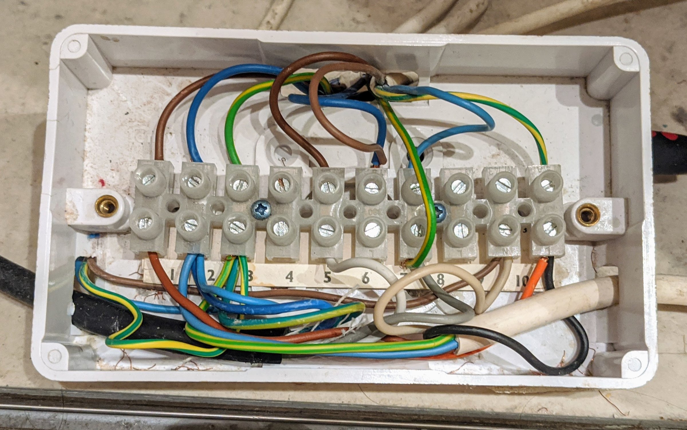
The only way I can get HW on is to turn off the heating at the fuse, thus resetting the valve to the default position. As soon as I add CH, HW gets turned off and even when CH reaches the optimum temperature and HW on, it still does not come on only a fuse reset will do this.

I have a newly installed nest system, replaced the valve head and the boiler stat, but still no impact. I have checked voltages on each wire and I think they are correct (not 100%).

Does this point to a wiring error I have not found or is the value faulty (it does seem to turn ok).

Suggestions welcome.
 
Sponsored Links
I think the most likely cause is that it has been wired incorrectly in that the grey wire to the motorised valve is being made live when it shouldn't be.

The grey wire is the 'hot water not required' signal and when made live, it winds the motorised valve fully across to close off the outlet going to the hot water cylinder.

The grey wire should only be connected to Nest Heat link terminal (4) 'Hot water satisfied' and also to the hot water cylinder thermostat 'Satisfied' terminal. (ie the terminal that becomes live when the hot water has reached the required set temperature) From these two points the grey wire is only 'live' when the hot water is off at the Nest, or the hot water cylinder has reached its set temperature.

If the grey wire is connected incorrectly to the central heating wiring and is being made live when the heating is switched on, as a result it will then shut the hot water off.

There could be other faults and/or a combination of faults, but I would start with this.
 
The motorised valve has two micro switches
mid-position-valve.jpg
grey does nothing until the motor gets to half way position and is normally dead until the demand for domestic hot water from the programmer is turned off, or if on the demand from the tank thermostat is off, so under correct operation the orange wire is paired with the supply from the tank thermostat on, so the power through the two resistors is not enough to cause the valve to motor, and as you have found the valve does not move and you get DHW.

When white has power it moves valve half way, through the SW1 switch, at half way the switch opens and the valve is now held in a stalled position with the diode and 13kΩ resistor, if DHW is NOT required then grey is made live, this then moves valve all the way, and SW2 closes and powers up the boiler.

So it would seem the grey wire is being energised when it should not be, with the standard Y plan there are as said two ways the grey wire becomes live,
Y-Plan.jpg
the time controller will have been replaced with Nest but still wired the same
upload_2017-8-25_10-21-19-png.125666
so the contacts are change over so it should be impossible for 4 and 6 to become live at same time and unless that happens you can't get live to grey and live to com, also water tank sensor N/O and N/C can't become live at same time so again grey can't become line when N/O is line, so neither Nest or the tank thermostat can cause the problem which is the grey becoming line, so looking at crushed cable, water ingress or incorrect wiring.

I would remove grey wire to motorised valve and put it in a connector block safe so can't touch anything and see if the DHW then works.

Note there is no need for anyone to follow the order of wires in the junction box.

I would look at the Nest heat link to see if any strand has ended up shorting 4 to 5.
 
Sponsored Links
It's busy I know...

Black cable is valve, white on right from boiler, pump cable comes in from left and in from top is power, boiler stat and wires from nest, thanks.
 
It's difficult without knowing what is on the other end of each wire. However as per my previous post regarding the grey wire from the motorised valve's black cable.
The grey wire should only be connected to Nest Heat link terminal (4) 'Hot water satisfied' and also to the hot water cylinder thermostat 'Satisfied' terminal. (ie the terminal that becomes live when the hot water has reached the required set temperature)

It appears that the grey wire from the motorised valve goes to terminal 7 in your photo below.

IMG_20200312_215525.jpg


Can you confirm where the two other wires (green/yellow & Blue) are physically connected at the other end. They should go to:

1. Nest Heat link terminal (4) 'Hot water satisfied' and
2. The hot water cylinder thermostat 'Satisfied' terminal.
 
Hi, the green/yellow does go to Nest ter 4, HW OFF. The Blue goes to the Boiler thermostat. The brown from the boiler Stat goes to terminal 6.
 
As per advice above I removed grey wire and HW works on demand. I subsequently got the voltages of Blue and green/yellow when disconnected and the green/yellow from ter 4 in Nest constantly has 240V.
 
Still cannot be correct.
Blue should go to either...

1. Nest Heat link terminal (4) 'Hot water satisfied' and
2. The hot water cylinder thermostat 'Satisfied' terminal.
As already pointed out.

I don't think anyone advised the removal of the grey.
Without that CH "only" is not available.
Post 4 shows it very clearly.
 
Sorry Vincent, I don't understand most of that. Whilst there will be wires that go the the boiler [usually a permanent live a switched live and a neutral]. The boiler thermostat is an integral part of the boiler control / PCB system, there shouldn't be any external wires going directly to the boiler thermostat.

However....
the green/yellow does go to Nest ter 4, HW OFF. The Blue goes to the Boiler thermostat.
....is wrong, the grey wire should go to
1. Nest Heat link terminal (4) 'Hot water satisfied' and
2. The hot water cylinder thermostat 'Satisfied' terminal.

The hot water cylinder thermostat 'call for heat' terminal should go to the boilers switched live. Check that you don't have the cylinder thermostat wired in backwards. ie 'call for heat' and 'satisfied' the wrong way around.
 
Last edited:
Thanks for all the advice guys. The removal of the grey wire allowed me to test turning on HW with CH on or off. As this worked it meant HW off what always being triggered. Testing the voltages on yellow/green (from Nest) and blue from boiler stat I found yellow/green always 240V regardless. There was a single stray wire in the heat link ter 5 that I doubt was shorting 4 but I rewired regardless and it seems to have done the trick. HW off triggered at the correct point.

NB. After a power up a Nest HW boost is not recognised (threw me).
 
Those wiring centre connections need reconfigured with either coloured tape or coloured cable sleeving so it's clear what is what.
 
I just copied this from the archives....

"It would also NOT be acceptable to use 3 core flex x 2, partly because it is not permitted to use the indicated earth conductor for other purposes, even if marked with red sleeving.
ChrisR"

https://www.diynot.com/diy/threads/...e-cable-for-honeywell-7-day-programmer.31878/

Wired one of these last week and connected an earth to live.
It was taped with red tape at the boiler and green/yellow at the airing cupboard.
Blew out the boiler stat. And surprised I didn't do far more damage tbh.

Anyway qualified sparks seem to think its OK.
Whats wrong with using numbered multi core and leaving a diagram?
OOh and the short cables on the ZV ? Everything left virtually inaccessible stuffed into a tiny junction box at floor level.
From what I've seen I think a lot of these so called "qualified sparks" are just cable draggers and glorified fitters.
 
Last edited:

DIYnot Local

Staff member

If you need to find a tradesperson to get your job done, please try our local search below, or if you are doing it yourself you can find suppliers local to you.

Select the supplier or trade you require, enter your location to begin your search.


Are you a trade or supplier? You can create your listing free at DIYnot Local

 
Sponsored Links
Back
Top