Remote controlling star delta starter

1 DP relay should do it if you think that there is no need for a time delay..

one set of N/O contacts goes in parallel with the start button ( S11.1), the second set of N/C contacts goes in series with the Q11/5 contacts (13 & 14 ).

This means that the starter is only held on by the machine contacts..

it is preferable though that the N/C contacts remain open for a second or so when the machine contacts open so that the starter Q11 doesn't manage to latch itself on..
 
Sponsored Links
Well I tried it with a DP relay and unfortunatly the relay is too quick and although it works on paper, the relay is too quick and the contactor is managing to latch on.

Oh well, it was worth a try.

I'll get a on pulse and an off pulse module and stop messing about :LOL:

Thanks for all your help though chaps.
 
Sponsored Links
holmslaw.. it's not a latching relay, it's a latching contactor / starter..
every single starter is self latching or you'd have to hold the start button on all day..
it's entirely electrical and not mechanical so in the event of a power failure it doesn't restart.
 
Rob,
Do you need to be able to run the vacuum pump indepentantly of the other machine?
If you want to run them together the method I described above is fairly simple:
 
This doesn't sound right to me.

The only time you would use latching relays on mechanical equipment would be if the dangers of the equipment stopping outweighed the dangers of it continuing to run. Also if the control circuit fails the pump will continue to run, how can you turn it off? via a local isolator? is it designed to be opened on full load current. And after a power failure the pump will auto re start.

Also the schematic does not show any mechanical interlock on the star delta contactor.

I'd be doing a bit more investigating before fiddling with the controls, it all looks a bit dodgy to me. Did the farmer design the cortrols? :)

Pumps automatically stop and start all the time and in many situations
but they should have local isolation
star/delta locals also tend to have an extra aux contact wired into the control circuit that drops the delta contactor out on switching it off (this is for situations where the contactors are in a remote panel in a BMS controlled plant room for example)

Oh and that is a standard star/delta starter control circuit BTW

RF if you still want to keep the manual starter then all you need is a three position changeover switch switch

One of these would do
I will cut a copy of the circuit shown and paste it back adjusted

Matt
 
holmslaw.. it's not a latching relay, it's a latching contactor / starter..
every single starter is self latching or you'd have to hold the start button on all day..
it's entirely electrical and not mechanical so in the event of a power failure it doesn't restart.

Wotalarf.and some donut has employed you wiring up control panels no wonder you've been sacked.

The standard control circuit has a hold on circuit/coil thats why millions of people around the world are not employed to press start buttons eight hours a day.

In this circuit the hold on coil is Q11.

did you read what you put earlier?
you were the one talking about latching relays and the motor restarting after a power failure..

perhaps I didn't express myself clearly but I am well aware of how starters work thank you..

Q11 is the coil for the main contactor, not a "hold on coil"..
the contacts Q11/5 ( 13 & 14 ) are the ones that hold the coil of Q11 on..

you also say that the drawing shows no mechanical interlock.. how do you know? we can't see all of it and if you look to the left of the drawing it shows part of the wiring for the actual contacts.. which might very well show a mechanical interlock...
 
There you go

View media item 29079
The DOL starter will operate as normal when in the hand (manual) position
in auto the remote machine will do all start/stop operations the buttons will have no effect
the off position will prevent either systems from working

if you really want the stop button to work in both situations(can't see why) then that can be done pretty easily too,
Let me know

Matt

Ok was up late with the brat so did one anyway
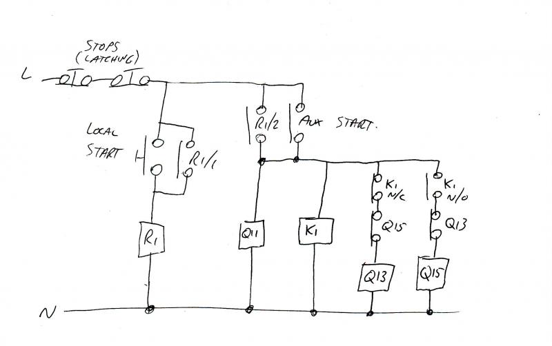
as well as the change over switch you will req a double pole relay and if you want an off position on the selector switch then you will req a double pole one of those too

View media item 29081
As before The DOL starter will operate as normal when in the hand (manual) position
in auto the remote machine will do all start/stop operations but this time the stop button will stop the pump
after the use of the stop button or off position then the start button will have to be operated to "reset auto" (to relatch K2)
you could wire "manual on" warning light to the spare terminal on the switch if you like
and a "auto on"one to the A1 side off the k2 relay contacts while your on
then If you are wanting to be really fancy, and if K2 is a changeover type and its common is put opposite A1 (A1 on n/o) then use the unused n/c contact to supply a "auto reset req" warning light :)

the off position will prevent either systems from operating

Its actually not much of a modification when you get down to it not a lot to do at all really
you are removing the link on Q11 beween terminals 14 and 54 and connecting the switch to them (com on 14 manual on 54)
the auto side of the switch you wire to K2's coil and to the com of one of its normally open contacts
the other side of this contact goes via the other pole of the switch to Q11's terminal13 then loops back to the com of the other set off K2's n/o contacts
now you connect the remote machines aux switch between this sets n/o contact and anywhere along the manual switch line (common toQ11 terminal 54)

hope that helps,
Matt
 
I'd put it after S11.0, this will retain the emergency stop function that your's removes..
 
Q11 is the coil for the main contactor, not a "hold on coil"..
the contacts Q11/5 ( 13 & 14 ) are the ones that hold the coil of Q11 on..

you also say that the drawing shows no mechanical interlock.. how do you know? we can't see all of it and if you look to the left of the drawing it shows part of the wiring for the actual contacts.. which might very well show a mechanical interlock...

Agreed,
this is only the control circuit,and only shows electrical interlock
Q11 is the main contactor
Q13 is the star contactor
Q15 is the delta contactor
K1 is the timer relay
F2 at the top is the O/L normally closed aux contact
All connections shown are coil and AUX contact connections
the motor connections are on the drawing to the left in the photo (you can see the star conntactor)

Matt
 
I'd put it after S11.0, this will retain the emergency stop function that your's removes..

S11.0 is not an emergency stop

its a normal stop, it doesnt latch, thats why I wouldn't put it after
but adding one before the stop switch wouldnt be a bad idea if needed

Matt
 

DIYnot Local

Staff member

If you need to find a tradesperson to get your job done, please try our local search below, or if you are doing it yourself you can find suppliers local to you.

Select the supplier or trade you require, enter your location to begin your search.


Are you a trade or supplier? You can create your listing free at DIYnot Local

 
Sponsored Links
Back
Top