Vaillant 438 with 3 zones, frequent S53

Status
Not open for further replies.
Ok, experimented a little tonight, and could do with a bit more expert advice:

If there were indeed a flow problem, would the furthest rads get hot at all ? As said, all rads do get hot once the system gets going.

Whilst flow through the system may be one aspect to this, Im wondering whether because it is simply such a large system, the return temperature creeping up is what one should expect. To test this, I tried turning off the furthest rads, as it's obvious which ones they are. I expected the return temperature to start going up at a more rapid pace, if indeed the pump was undersized, but it doesn't. In fact, it goes up precisely the same amount as I timed each degree increment. Not sure how scientific this is.

Instead, Im leaning towards this theory: The d/s zone totals just under 26kw. The u/s zone totals just under 19kw. Given I have range rated at 26kw, maybe this is why the u/s sees S53s. The return temperature going up slowly may be one cause of this, but the other may be that there is too much power being delivered for the u/s circuit on it's own. Does this make any sense ?

If this is the case, Im concerned that if I range rate to 18kw, how will the system behave with both u/s and d/s opening up simultaneously. I'll try the lower setting tomorrow.
 
Sponsored Links
Well as long as you are enjoying yourself!

Tony
 
Not exactly!

Any advice on what I said above Tony ? Or am I just talking nonsense ?
 
I haven't bothered to read all the postings but from what I've seen there's some really basic design issues that aren't being adressed...

Heating design appears very simple but can rapidly get more complex. Proper design is rarely done in a domestic environment for a variety of reasons.... most installers are incapable of the calculations, it takes a considerable time to do all the calculations, without ripping apart an existing installation it can be difficult to work out the pipework (in particular index circuits etc), radiator outputs are difficult to ascertain (especially with old types/styles), building fabric construction can be impossible to ascertain (without knocking holes through walls), manufacturers information is sometimes lacking in detail, technical lines are often hopeless and above all most homeowners simply wouldn't pay for a day(s) of calculator work.

So just a few basic considerations (but leaving out some of the finer points)....

Calculate the heat loss from the house...what the radiators add up to is irelevant, it's the fabric of the building and it's contruction that determines heat loss.

Traditional system design dictated an 11 degree drop accross the radiators/boiler at worst case temperatures ie. at say 18 to 21 degrees room temps and say -1 outside. This 11 degree drop was based on the old Farenheit temperature drop of 20 F and was derived at for a variety of reasons.

Now due to pressure to save energy (pump energy) and modern heat exchanger design (they are often very restrictive) there has been a move away from the 11 degree drop towards a 20 degree drop. Allowing a larger temp drop means the water will be circulating slower and will give off more heat energy as it cools. It also results in an increase in the heat carrying capability of the pipework at the same circulating volume. However, the average temperature of the radiator will drop. If some or all of the radiators have been sized correctly based on the old 11 degree drop then increasing the temperature drop will mean they will give out less heat. This may only be noticable once outside temperatures dip down to freezing. A compromise might be to try an achieve a 15 degree drop.


Once you know the heat loss from each room you can ascertain whether each radiator is sized correctly.

Now you need to calucate the index circuit ie. the pipe run/radiator network with the highest resistance. It's often the furthest/largest radiator.
The head loss (ie. the meter height of water) resistance of the index circuit is dependant on the temperature drop across the radiators/boiler. I suggest you calculate based on a 20 degree drop for now. If the radiators are undersized they will struggle to heat the rooms once it's very cold outside. Calculating at 20 degrees and getting the system working reasonable well is the main aim for the moment. The Vaillant boilers along with other manufacturers have modern heat exchangers with highly restrictive heat exchangers. Without massive circulators achieving an 11 degree drop at worst case scenarios is almost inpossible, a 15 degree drop may be feasible.

With the index circuit calculated we know the maximum head loss (in meters) at the required flowrate (in say litres/hour or cubic meters per hour) of the radiator circuit.

With traditional boilers (say the old cast iron and many copper) resistance through the boiler could be ignored. With most cast iron the waterways were huge, with copper fabrications it was simply a few copper pipes. With these boilers we could simply look at a pump chart, find the flowrate along X axis, find the index circuit head loss along the Y axis and see where the lines intersect. If the point was below the speed curve selected the circulator was suitable. For the majority of domestic properties a 5 or sometimes 6 meter circulator was suitable (since heat exchangers had little friction) and as a result calculations of index circuits were largely redundant.

As mentioned before, the latest generation of boilers have heat exchangers of a completely different design than the old cast iron and copper fabricated designs. They are either manufacturered from stainless steel formed tubing or cast aluminium. In order to increase the heat transfer and reduce the physical size/weight the waterways are incredibly fine. In the case of the Giannoni fitted to the Vaillant, the heat exchanger approximates three 12mm (a bore only 10mm) soft copper tubes connected in parrallel perhaps around 1.5 meter in lenght. If this was bad enough they are formed into a tight spiral, the boilers internal pipework is often only 18 to 22mm diameter tube containing multiple tight bends. Trying to circulate water through heat exchanger as a rate to allow us to have the traditional 11 degrees drop would require a massive pump. Even circulating water at a slower rate to achieve a 20 degree drop still results in a significant head loss.

Therefore the headloss through the heat exchanger MUST be taken into account. Unfortunately most installers fail to understand this and most manufactures pay scant regard to this problem either. It's in part due to the cover up about condensing boilers...ie. that they no more difficult to install than the older boilers. Of course it's anything but when you have to use commercial pumps or low loss headers in a domestic environment and have an installer base that has little design knowledge (or even care).


There's a simple calculation to provide the flowrate at a particular temperature drop and heat output.

Flowrate in litres/second = Kw output / (4.2 x temperature drop)

For the flowrate in litres per minute obviously multiply by 60 or litres per hour by 3600.

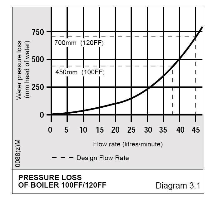
Just as an example here's the headloss graph for an old Glowworm Ultimate heat exchanger. The 120,000 Btu is around 35 Kw (so similar to your Vaillant). The dotted line from the 120FF shows the flowrate (45 litres/min) at the traditional 11 degree drop and a corresponding head loss of just under 0.75 m. However if we recalculate at 20 degrees drop the flowrate will be 25 litres/min and a head loss of 0.25 m.


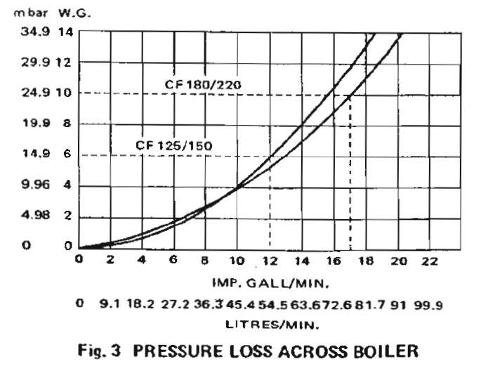
Now plug a 20 drop across the ancient Potterton CF125/150 heat exchanger and at a similar Kw output we get a head loss of under 0.05 m!


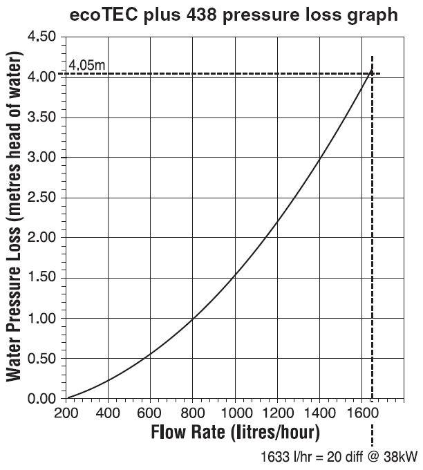
Now compare these old heat exchangers to your modern Vaillant....

At the 20 degree drop and the boiler output of 38 Kw we get a flowrate of 1628 litres/hour (approx). Look at the heat loss...it's massive at 4 m.


If we recalculate at 15 degrees we are off the scale and the head loss is vast, at 11 degrees...forget it. This is just another part of the great condensing boiler cover up, the public and installers have been conned into thinking modern boilers are reliable and easy to install compared with the older generation boilers.


http://www.anchorpumps.com/media/downloads/75/Grundfos Light Commercial Circulators.pdf


So if we take a standard UPS 15 60 a 6m domestic circulator and look at the pump diagram we can see it will barely circulate the required water volume through the heat exchanger. At 20 degrees drop, 1633 litres/hr is 0.45 litres/second. Follow the flowrate up from the X axis on the pump diagram until it hits the curve at speed 3. Going horizontally from that point it hits the Y axis at about 3.5m. So at that flowrate it can only overcome a head loss of 3.5m. There is no spare capacity to overcome the system index circuit.

With the UPS 25 55 looking at the pump graph at 0.45 litres/min it provides a head of 4 meters...a little more than the "domestic" pump. So it would be sufficiently powerful enough for the flowrate through the boiler at a 20 degree drop but again not once the additional index circuit is added. Of course this is a second hand pump so its actual performance is debatable.

So with the boiler head loss diagram and the index circuit calculated the overall flowrate and head loss can be derived. It's then just a case of matching a pump(s) to the system.

Ignoring low loss headers (it gets much more complicated) the option either is one large pump or a couple of pumps in series. Larger pumps greater than domestic duty rapidly increase in cost so it can be more cost effective to use muliple pumps in series (where the head figure at a given flowrate can be added together).

Adding both pumps together in series as you have done for the downstairs circuit would appear to have gone someway to solving the circulation issue. So the cheapest option for now is to move the new UPS 15 60 pump and connect it next to the UPS 25 55 so that all zones are operating with both pumps.


As has been mentioned (after the usual nonsense has been posted) the first figure on a Grundfos pump refers to the nominal bore of the pump, the second figure refers to the approximate maximum head in meters (AT NO WATER FLOW so is irrelevant), and where qouted the third figure is the mm distance between fittings. Most domestic are 130mm and commercial 180mm.


Just a few other points...

There should be a lockshield valve fitted to the cylinder primary pipework in order to restrict the flow rate when the heating circuits are operational.

Balance the system to achieve the same temperature drop across all the radiators/cylinder.

Hopefully the basic pipework is reasonably well sized for the heat loads and lenght.

It's benefical to run the boiler flow temperature lower that it's maximum but it needs to be sufficent to heat the cylinder to 60 degrees. Only when outside temperatures are severe will the temperature need to be increased to maximum (if the radiators were sized with high flow temperatures). This iss where they are some benefits in oversizing radiators since they wil still give off sufficient heat when average rad temperatures are lower.

Forget any suggestions of changing boiler circuit boards or weather compensation controls....you have to get the basics right first.

Make sure the system is dosed correctly with inhibitor, moedrn heat exchangers are less tolerant to corrosion and scale/sludge. Once they block the boiler is often a write-off.

It may be winter before you can really ascertain whether you can achieve the desired temperature drop and if at that drop the average radiator temperature is sufficient to heat the rooms. At this time of year when outside temperatures are rarely dropping below 10 or 12 degrees (certainly in London) at night, you can't judge whether the system is really going to work until it's snowing. Many installers install new boilers in the warmer months and leave what appears to be a working system (all rads heat up nicely) but come the winter it fails to heat the house up simply because the water is not being circulated in sufficient volume and the raidators dissapate more heat.
 
Sponsored Links
vaillant have modified the software on the 400 series boiler to make it more tolerant of lower loads...apparently it will resolve this issue with on-off controls, it certainly does with compensation controls.

Condensing boilers have to be flow rate tolerant, as TRVS will always vary the flow rate through the boiler, as do zones.

With a header you can maintain a fixed flow through the boiler and variable flow through the radiator zones...

Vaillant would not modify a board if it did not need it... my bet is that a simple change of the PCB resolve the OP faces..
 
GasGuru, that is a very informative post, thanks very much for taking the time to post that. Im not sure if Im able to use it to solve my immediate problems, but it at least gives me a better understanding on pump size and why my u/s zone flow may not be sufficient.

I have an update on further experimenting today. It seems that my u/s flow isnt sufficient, and could probably do with a larger pump to drive the whole system. This is something I will want to try at some point, negating the need for a second pump on the d/s. Alternatively, adding a second pump to the u/s.

I dont think my S53 is to do with flow though. The reason being that if I turn off a couple of radiators on the d/s zone, I get S53s there too, and I know I have plenty of flow there with the second pump. It seems to me the Vaillant's software isnt very intuitive. Surely it would make more sense to have the power output ramp up slowly, rather than starting at full and then modulating down (which doesnt always seem to work). OR, to use an S53 as an indicator that on the next fire, the power should be reduced and then slowly ramped up.

The other major problem is how to range rate to cater for one zone or all zones simultaneously. Im not sure if there is a correct answer to this other than trial and error.

So what Ive done now is to range rate to 18KW (the total rad output for u/s). Total rad output for d/s is 26KW. This seems to solve the S53 whether I run a single zone, or all zones simultaneously. I've also found that turning off the radiator on the u/s index circuit results in the return temperature for u/s rising more rapidly. I measured this to be 1 degree every 60 seconds, whereas with the index circuit rad open fully (Im sure Ive read in the balancing faq that the last radiator in the circuit should have it's l/s open fully, though I could be wrong) I was getting 1 degree increase on the return every 120 seconds. So to compromise Ive reduced the flow to this last rad, and found it still warms up without having it's l/s fully open. The return temperature also rises a degree approx every 80 - 90 secs.

So no more S53s it seems. Both u/s and d/s get fully hot independently. With both u/s and d/s running, the d/s rads get fully hot within 15 mins. The u/s rads are slower to warm up, though, and werent fully hot even after 40 mins. Now Im unsure if this is a) because the d/s has far more flow and taking more of the heat away, or b) because the boiler is not outputting enough power for all 20+ radiators simultaneously. But at least the system is working better than it was. I'll be balancing properly once my thermometer probes arrive.

Do you believe that having far more flow on one zone compared to the other is a bad thing in general, and that I should boost flow on both zones equally. Moving the second pump before the zone valve is unfortunately not an option, as there is insufficient space for it. So I'd have to invest in a bigger pump.
 
vaillant have modified the software on the 400 series boiler to make it more tolerant of lower loads...apparently it will resolve this issue with on-off controls, it certainly does with compensation controls.

Condensing boilers have to be flow rate tolerant, as TRVS will always vary the flow rate through the boiler, as do zones.

With a header you can maintain a fixed flow through the boiler and variable flow through the radiator zones...

Vaillant would not modify a board if it did not need it... my bet is that a simple change of the PCB resolve the OP faces..

Alec, any info on obtaining this new PCB would be great. Is it a case of getting an engineer out and then fighting for it, or is there an easier way ?
 
as said, speak to vaillant...your installer shoild be able to help too...
 
As I said commercial pumps are hugely expensive and running a couple of domestic pumps in series is cheaper.

I also said to calculate the heat loss....again you are basing the heat loss on the size of the rads...completely wrong.

Post a picture of the pumps....can't beleive there isn't sufficient space to fit the pump.

Range rating the heating down is pointless..what are going to do when you need the boiler to operate at the higher output when the winter comes and all zones are required.

Given you have range rated the boiler to 18Kw and claim the downstairs circuit is 26Kw the fact that it heats up fully in only 15 mins even in this weather would indicate to me that the actual heat load is a fraction of what you think. If you genuinely need 38Kw that's one huge house and probably a detached Victorian.

Have a look in the manual...use D40 and D41 to display the flow and return temperatures. AFAIR once the differential hits 30 degrees it will initiate the S53 wait.

Get the basics right before pcbs :)
 
The heat loss calc was 36Kw, as said. It's a solid wall house, with a cavity and modern insulation only in the new extension. The loft is fully insulated though.

The radiators I purchased myself and total to 44Kw (according to kw output on screwfix's website). They are all Kudox branded. The split is 26kw d/s, and 18 kw u/s. Short of attaching receipts for the purchases here, not sure what else I can do to convince you that my claim is based on fact!

I, too, am confused how 26kw of radiators can get fully hot when the boiler is range rated at 18kw. But then there's factors which come into play which I dont fully understand, such as radiators being x% efficient at certain temperature differentials etc, so maybe the actual load isn't what the manufacturer stated load is.
 
Get the basics right before pcbs :)

One thing I would say, though, is that I think my problems stem from the multiple zones. If the boiler behaved in a more sensible manner and could be configured for different power outputs for individual zones, or all combined, then this would negate the need to range rate it to cater for the lowest powered zone.

So possibly the pcb may fix that.
 
I haven't bothered to read all the postings but from what I've seen there's some really basic design issues that aren't being addressed.
...
A very informative post.

I just wonder how much of that is actually taught to trainee heating engineers - and I'm not thinking of the 'six week cowboy' courses.
 
With the UPS 25 55 looking at the pump graph at 0.45 litres/min it provides a head of 4 meters...a little more than the "domestic" pump. So it would be sufficiently powerful enough for the flowrate through the boiler at a 20 degree drop but again not once the additional index circuit is added. Of course this is a second hand pump so its actual performance is debatable.

Just reading your post in more detail, and a few points I'd make re my setup:

1) The 25-55 is brand new, fyi. I did try a larger pump which was second hand, and it's performance was no better, perhaps worse. But it was in pretty bad shape. The reason I think this may be significant is in point 2 below.

2) Given the pump heads and your brilliant post, I'm "guessing" that my pump may in fact be reasonable for my index circuit. This is because even with my 15-60, my radiators were still heating up. I had an unrelated problem to do with a faulty ABV during which I changed the pump. I do believe though that the 15-60 would have sufficed as well once the ABV was fixed.

3) Whilst I dont know the resistance of my index circuit (and am struggling to find any links to literature to work it out, as I know the pipe diameters, length, bends etc etc), it's clear Im not using the full capacity of my boiler, as Im range rating it down because of the S53 issue. This means at 18KW, my required flow rate is:

18 / (4.2 * 20) = 0.21 l/s.

This means the 438's pressure loss is less than 1m of head, leaving far more available for the index circuit.
 
Vaillant have modified the software on the 400 series boiler to make it more tolerant of lower loads...apparently it will resolve this issue with on-off controls, it certainly does with compensation controls.

Alec, could you be more informative about this please!

What is the part number of the modified PCB? Presumably its just a swap for the old one?

From what date ( serial number? ) have 400 series boilers been supplied with the modified PCB?

How can you visually identify this modified PCB?

Tony
 

DIYnot Local

Staff member

If you need to find a tradesperson to get your job done, please try our local search below, or if you are doing it yourself you can find suppliers local to you.

Select the supplier or trade you require, enter your location to begin your search.


Are you a trade or supplier? You can create your listing free at DIYnot Local

 
Status
Not open for further replies.
Sponsored Links
Back
Top